


80
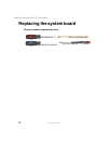
Replacing Gateway 400VTX Components
www.gateway.com
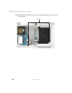
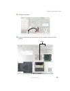
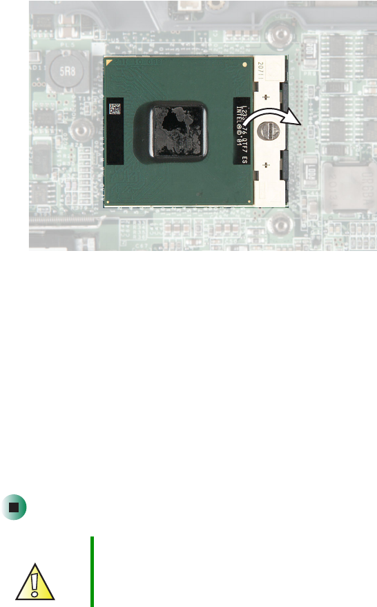
25 Install the processor onto the new system board making sure that Pin 1
on the processor (indicated by the silk-screened arrow on the corner of the
processor) aligns with Pin 1 on the processor socket (indicated by the
absence of a pin hole in the processor socket), then use a flat-blade
screwdriver to turn the processor lock screw 1/4-turn clockwise.
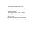
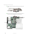
26 Place the new system board into your notebook.
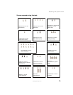
27 Replace the four black system board screws into the holes marked 2, 7, 19,
and 21, and the hex nuts into the holes marked 5 and 6.
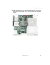
28 Replace the four hex nuts on the rear I/O panel.
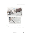
29 Turn the notebook over and replace the two chrome screws on the bottom.
30 Turn the notebook over and connect the speakers.
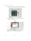
31 Reassemble your notebook.
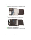
32 Place a new wireless Ethernet label on the mini PCI cover so it covers the
screw.
Caution By law, a wireless Ethernet FCC ID and security label must
cover the mini PCI cover screw. End users are strictly not
permitted to have access to the wireless card.