


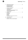
LX: OPM_LPU_11U_5K0_10K_1US_V030 11 GE DE LP 11U UPS: Installation / User Manual 3.0 (US)
Digital En
e
rg
y
™
LP Serie
s
g
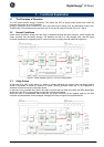
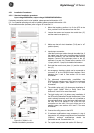
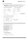
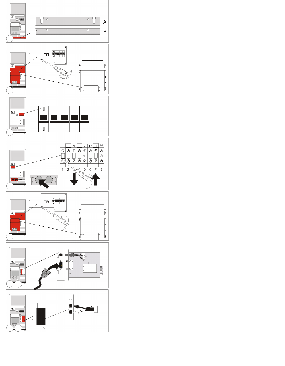
4.5.1 Installation Procedures
4.5.1.1 Standard installation procedure:
input voltage 208-240Vac, output voltage 120/208/220/230/240Vac.
If a battery extension pack is to be installed, please proceed with section 4.5.5.
If 2, 3 or 4 parallel operating units will be installed, please proceed with section 4.5.6.
The numbers between (brackets) refer to figure 19 in section 5.1.
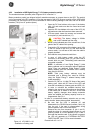
1. Mount the levellers: position A to fix the UPS to the
floor, position B to lift the castors from the floor.
2. Loosen the screws and remove the conduit box (17)
and the metal cover plate (11).
3. Make sure that all circuit breakers (7-8-9) are in ‘off’
position (down).
4. Input/output connection:
Lead the input/output cables through the cable inlet. If
the cables come from below (recommended for 8kVA
and 10kVA models), you can rotate the cable inlet 90
degrees. Connect the input/output wires to the I/O
terminals (11a and 11b). Please refer to section 4.5.2
1 (input) and 4.5.3 (output) for detailed information.
5. Re-install the metal cover plate (11) and the conduit
box (17).
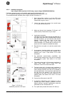
6. An emergency shutdown switch can be connected to
connector J3 on the RS232/Contact Interface Card,
between pins 3 and 4. See section 6.2 for more
information.
7. For advanced communication possibilities, the
RS232/contact interface port (12a) can be connected
to a computer system. See section 6.1 for more
information.
8. The middle ‘option slot’ (13) allows easy installation of
plug-in cards: SNMP Card or Relay Card. See
sections 6.3 and 6.4 for more information.
9. The right ‘option slot’ (14) allows easy installation of
the RPA-card (Redundant Parallel Architecture). If the
card is already mounted, and if the unit is intended to
be used stand-alone, a bus terminator (delivered with
the unit) has to be placed in one of the two bus
connectors on the card. If the unit will be part of a
parallel system, see sections 4.5.6 and 7.3 for more
information.
10. Connect the utility power to the UPS.
11. If hardware modifications were necessary in step 4
because the I/O voltages are different from the default
(208Vac), software modifications should be
performed as well. Proceed with 4.5.4.
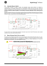
12. For a quick start proceed with section 5.2 ‘Start-up’.
Figure 6. LP 5/68/10
-
11U
:
Standard installation procedure
1
2
3
4
see 6.3-4
see 4.5.6 / 7.3
stand-alone
and RPA card
available
BATTERY
DISCONNECTED
EMERGENCY
SHUTDOWN
ON
OFF
5
6 7
8 9