


LX: OPM_LPU_11U_5K0_10K_1US_V030 28 GE DE LP 11U UPS: Installation / User Manual 3.0 (US)
Digital En
e
rg
y
™
LP Serie
s
g
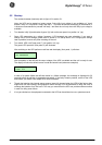
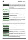
The output converter frequency is not synchronized to the utility (input)
frequency. In this situation the automatic bypass switch is not able to transfer
the load from output converter to bypass and reverse: automatic bypass
operation is inhibited: if for whatever reason the output converter is unable to
deliver the required output, output power is lost. (see section 3.5).
Synchronization is only possible if the utility frequency remains within certain
limits (see chapter 10).
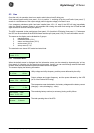
The remaining runtime. This figure is counted down during battery operation
until either the utility returns or the batteries are depleted.
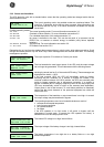
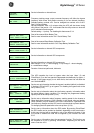
The output is switched off due to a faulty situation, indicated by the second
line.
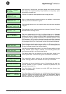
The output will be switched off by a remote command (RS232/SNMP). The
second line indicates the time until shutdown.
The output is switched off by a remote command (RS232/SNMP). The second
line indicates the time until wake-up.
The output is switched off by the 'no-load shutdown' feature: no input voltage
and load <2%. If the input voltage is restored, the output will be available
again. See also section 5.5.1
The wire on connector J3 pin 3-4 (rear panel, plug-in card 12) is interrupted.
The output is no longer available. To restart the unit, restore the connection
and turn the on/off switch (rear panel, 7) off and on again.
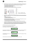
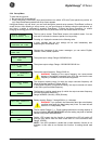
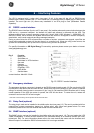
5.3.3 Service Menu
When the default screen is displayed you can enter the first service screen by depressing the keys 'down' (2)
and 'Enter/Reset' (3) simultaneously for approx. 1 second. Using the 'up' (4) and 'down' (2) keys you can scroll
through several service screens.
The intro service screen. 'Enter/Reset' returns to the default screen.
The serial number of the UPS.
Release number of the installed software and production code of the UPS.
Service information about fan speed (min. 10, max. 30) and internal DC
voltage.
Service information on internal temperature levels, values in mV over the
temperature sensors.
First line: service information on charger. ‘1’ = batteries have reached float
voltage.
Second line: service information on output converter.
INPUT AND OUTPUT
NOT SYNCHRONIZED
BATTERY RUNTIME
LEFT 0:09:41
OUTPUT OFF
NO INPUT POWER
PROG. SHUTDOWN
WITHIN 0:09:17
PROG. SHUTDOWN
LEFT 0:14:03
SHUTDOWN
ALARM PRESS UP
IMMEDIATE
SHUTDOWN
SERVICE SCREENS
ENTER exit
SERIAL NUMBER
l051U01/0020A030
SOFTWARE VERSION
R2.9; 640777
FAN SPEED 10
INV.DC: + 375
HEATSI.TEMP: 0
TRANSF.TEMP: 310
FLOAT CHARGE: 1
OUTPUT FAST : 0