


LX: OPM_LPU_11U_5K0_10K_1US_V030 12 GE DE LP 11U UPS: Installation / User Manual 3.0 (US)
Digital En
e
rg
y
™
LP Serie
s
g
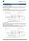
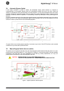
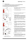
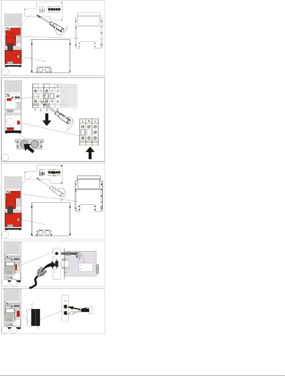
4.5.1.2 Installation procedure:
input voltage 120Vac (optional, 5-6kVA only), output voltage 120/208/220/230/240Vac.
If a battery extension pack is to be installed, please proceed with section 4.5.5.
If 2, 3 or 4 parallel operating units will be installed, please proceed with section 4.5.6.
The numbers between (brackets) refer to figure 19 and 20 in section 5.1.
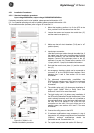
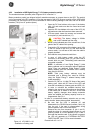
1. Mount the levellers: position A to fix the UPS to the
floor, position B to lift the castors from the floor.
Please refer to figure 6, step 1.
2. Loosen the screws and remove the conduit boxes
(17, 2x) and the cover plate (11).
3. Make sure that all circuit breakers (7-8-9) are in ‘off’
position (down). Please refer to fig. 6, step 3.
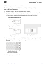
4. Input/output connection:
Lead the input/output cables through the cable inlet. If
the cables come from below (recommended for 8kVA
and 10kVA models), you can rotate the cable inlet 90
degrees. Connect the input wires to the input
terminals (11b). Connect the output wires to the
output terminals (11a). Please refer to section 4.5.2.2
(input) and 4.5.3 (output) for detailed information.
5. Re-install the cover plate (11) and the conduit boxes
(17, 2x).
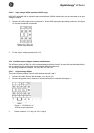
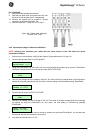
6. An emergency shutdown switch can be connected to
connector J3 on the RS232/Contact Interface Card,
between pins 3 and 4. See section 6.2 for more
information.
7. For advanced communication possibilities, the
RS232/contact interface port (12a) can be connected
to a computer system. See section 6.1 for more
information.
8. The middle ‘option slot’ (13) allows easy installation of
plug-in cards: SNMP Card or Relay Card. See
sections 6.3 and 6.4 for more information.
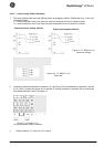
9. The right ‘option slot’ (14) allows easy installation of
the RPA-card (Redundant Parallel Architecture). If the
card is already mounted, and if the unit is intended to
be used stand-alone, a bus terminator (delivered with
the unit) has to be placed in one of the two bus
connectors on the card. If the unit will be part of a
parallel system, see sections 4.5.6 and 7.3 for more
information.
10. Connect the utility power to the UPS.
11. If hardware modifications were necessary in step 4
because the output voltage is different from the
default (208Vac), software modifications should be
performed as well. Proceed with 4.5.4.
12. For a quick start proceed with section 5.2 ‘Start-up’.
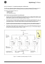
Figure 7. LP 5/6
-
11U
:
Installation procedure 120V input
2
see 6.3-4
see 4.5.6 / 7.3
stand-alone
and RPA card
available
BATTERY
DISCONNECTED
EMERGENCY
SHUTDOWN
4
5
6 7
8 9