


LX: OPM_LPU_11U_5K0_10K_1US_V030 13 GE DE LP 11U UPS: Installation / User Manual 3.0 (US)
Digital En
e
rg
y
™
LP Serie
s
g
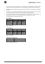
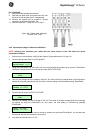
4.5.2 Available input voltages: hardware modifications
The following input voltages are possible: 208, 240 Vac (see 4.5.2.1) and 120 Vac (see 4.5.2.2)
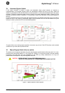
4.5.2.1 Input voltage 208 or 240Vac.
1. Input voltage is 208 Vac. This is the factory setting. Proceed with step 3.
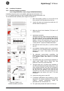
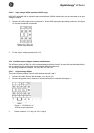
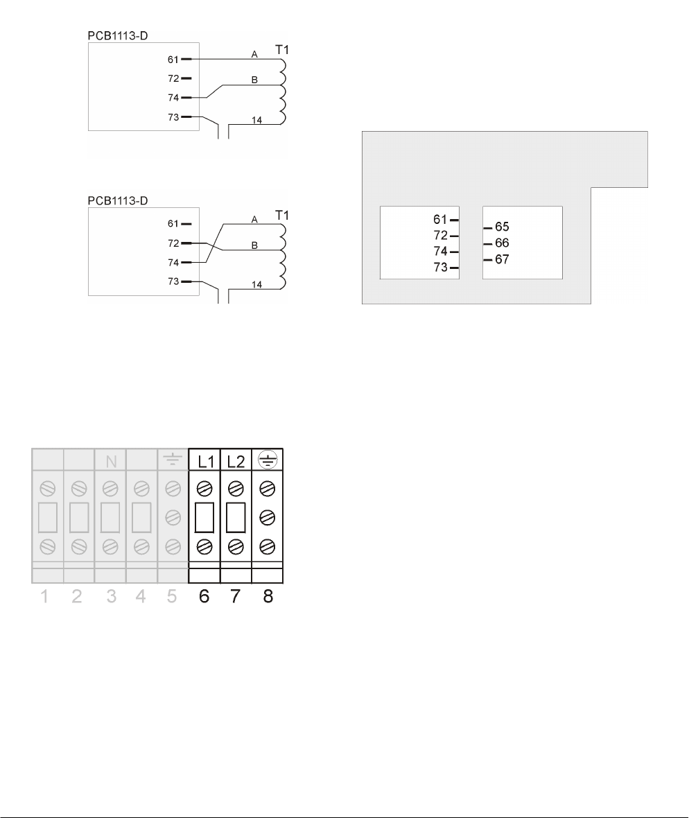
2. Input voltage is 240Vac. In this case the bypass tap on the output transformer must be changed. Please
refer to fig. 8 and 8a. Proceed as follows:
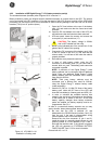
2.1 Remove the yellow wire B from faston 74 (connect) and place this wire on faston 72 (park).
2.2 Remove the blue wire A from faston 61 (park) and place this wire on faston 74 (connect).
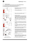
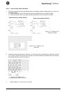
3. Connect the utility supply wires to terminals 6 (L1), 7 (L2) and 8 (equipment grounding conductor). See
figure 9. Ground connection is essential!
If a neutral wire is part of the site wiring provided, we suggest to isolate this wire for future use or other
applications.
4. For the output voltage proceed with 4.5.3.
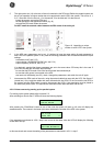
Figure 9. LP 5/6/8/10
-
11U
:
Output (grey) / input terminals
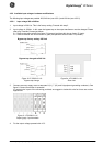
Figure 8. LP 5/6/8/10-11U:
Bypass tap change
Figure 8a. LP 5/6/8/10-11U:
Rear view
(p
ark
)
(p
ark
)
(
connect
)
(p
ark
)
(p
ark
)
(
connect
)
Bypass tap factory setting: 208 Volt
Bypass tap changed to 240 Volt