


LX: OPM_LPU_11U_5K0_10K_1US_V030 17 GE DE LP 11U UPS: Installation / User Manual 3.0 (US)
Digital En
e
rg
y
™
LP Serie
s
g
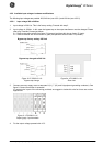
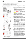
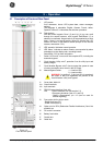
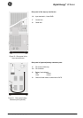
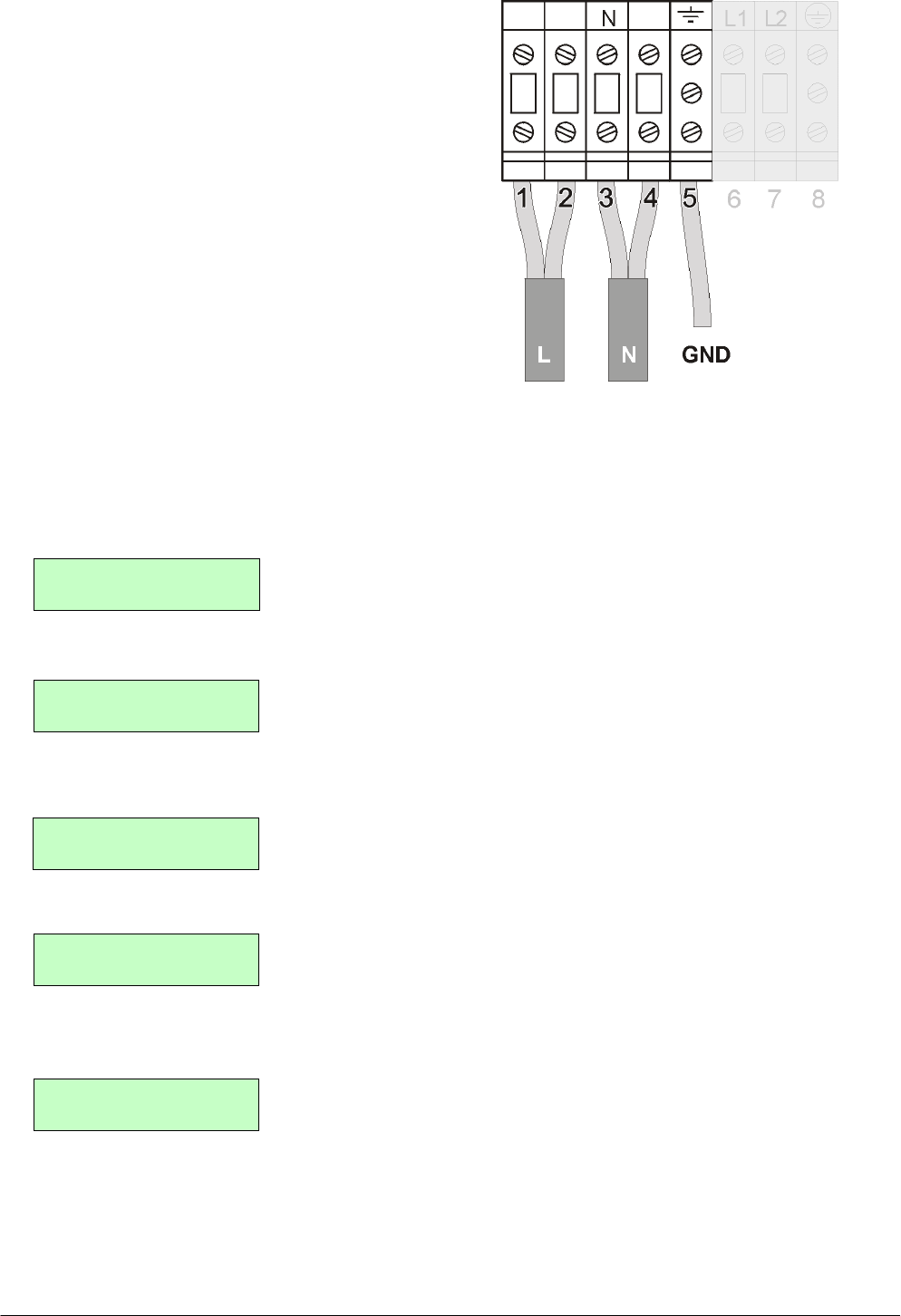
For LP 8/10kVA:
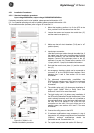
8. Remove all links between the terminals.
9. Split both the load wires and spread one wire over
terminal 1-2 and the other over 3-4 respectively.
10. Connect the ground wire to terminal 5. Ground
connection is essential! See figure 15a.
11. Return to either 4.5.1.1 step 5 or 4.5.1.2 step 5
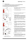
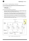
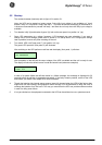
4.5.4 Input/output voltages: Software modification.
NOTE: following this procedure you realize that the values shown in the LCD match the actual
input/output voltages.
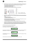
1. Switch on the circuit breakers 'utility' (8) and 'bypass' (9) (see also section 5.2, step 1-2)
2. Go to the set-up menu. See 5.3.4 ‘Set-up Menu’
3. Using the push-buttons 'up' and 'down' you can scroll through the several set-up screens. 'Enter/Reset'
confirms the screen choice. Go to the set-up screen 'INPUT VOLTAGE'.
4. Here you can change the input voltage to 240 Volt. The value of the input voltage blinks. Scroll through its
settings by using the push-buttons 'up' and 'down', the new setting is confirmed by pressing 'Enter/Reset'.
5. Go to the set-up screen 'OUTPUT VOLTAGE'.
6. Here you can change the output voltage to 240 Volt. The value of the input voltage blinks. Scroll through
its settings by using the push-buttons 'up' and 'down', the new setting is confirmed by pressing
'Enter/Reset'.
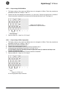
7. To return to the default screen scroll to the set-up screens first and press 'Enter/Reset'. You can also wait
20 seconds: the time-out period of no key activity.
8. You can now proceed with 5.1 or 5.2.
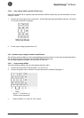
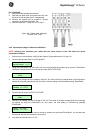
SETUP SCREENS
ENTER/RESET exit
INPUT VOLTAGE
208V
INPUT VOLTAGE
CHANGE TO
240
V
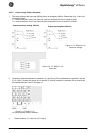
OUTPUT VOLTAGE
208V
INPUT VOLTAGE
CHANGE TO
240
V
Figure 15a. Output cable splitting for
8/10kVA 120V 2-wire