


LX: OPM_LPU_11U_5K0_10K_1US_V030 7 GE DE LP 11U UPS: Installation / User Manual 3.0 (US)
Digital En
e
rg
y
™
LP Serie
s
g
3.1 The Principles of Operation
The UPS stores electric energy in batteries. This allows the UPS to supply output power even when the
incoming utility power is cut off completely.
Energy is stored as Direct Current (DC), while input and output energy must be Alternating Current (AC).
Therefore the UPS contains an input converter (AC to DC) and an output converter (DC to AC). (fig.2)
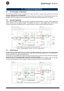
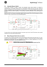
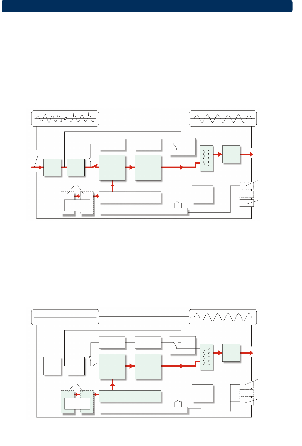
3.2 Normal Conditions
Under normal conditions, energy from the utility is channeled through the input converter, which supplies the
output converter and the battery charger. The batteries are kept in a fully charged state, and the output
converter synthesizes a completely new AC output sine wave to supply the load (electrical equipment).
3.3 Utility Failure
In the event of a utility power failure (i.e. absent or outside tolerance) the system uses the energy reserve
stored in the battery to continue to produce AC power, ensuring unbroken output (fig. 3). No interruption or
alteration will ever be noticed in the output power.
In the event of an extended utility failure, the output converter will stop when the battery has been discharged.
At this point, the UPS is no longer able to power the connected equipment.
When the utility is re-established within tolerance, the output converter will be supplied again by the input
converter and the batteries will be recharged, making them ready to support future power failures.
Figure 2. Block diagram of the LP 11U UPS, utility present
Figure 3. Block diagram of the LP 11U UPS, utility failure
3 - Functional Explanation
INPUT:
MAINS POWER WITH DISTURBANCES
BYPASS
FILTER
P.F. = 1
CONVERTER/
RECTIFIER/
BATTERY
CHARGER
BACKFEED
PROT.
OPTIONAL
BATTERY
EXTENSION
BATTERY
MICROPROCESSOR CONTROL
SYSTEM
ON/OFF
OUTPUT
CONVERTER
MANUAL BYPASS
SWITCH
UTILITY INPUT
OUTPUT:
PERFECT UPS POWER
RFI
FILTER
OPTION
SLOTS FOR:
RPA CARD
SNMP CARD
RELAY CARD
STANDARD
INSTALLED:
RS232/
CONTACT
INTERFACE
FRONT
PANEL
TO LOAD
RFI
FILTER
STATIC
BYPASS
OUTPUT
TRANSFORMER
NO INPUT:
UTILITY FAILURE
BYPASS
FILTER
P.F. = 1
CONVERTER/
RECTIFIER/
BATTERY
CHARGER
OPTIONAL
BATTERY
EXTENSION
BATTERY
MICROPROCESSOR CONTROL
SYSTEM
ON/OFF
OUTPUT
CONVERTER
MANUAL BYPASS
SWITCH
OUTPUT:
PERFECT UPS POWER
RFI
FILTER
OPTION
SLOTS FOR:
RPA CARD
SNMP CARD
RELAY CARD
STANDARD
INSTALLED:
RS232/
CONTACT
INTERFACE
FRONT
PANEL
TO LOAD
RFI
FILTER
STATIC
BYPASS
OUTPUT
TRANSFORMER
BACKFEED
PROT.