


PMCS Interface Toolkit Features of Tabular Data Screen Wizards • 151
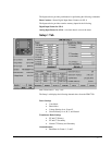
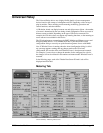
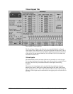
the active group currently in use by the relay’s protection algorithms. The
pushbuttons are subject to user level security in Intouch.
Phase TOC and IOC Settings
The Phase, Neutral, and Ground buttons in this section may be used to select the
display of the TOC and IOC values.
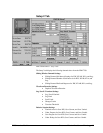
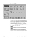
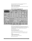
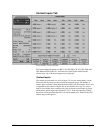
Power System Configuration Tab
Universal Relay - Power System Configuration Tab
The Power System Configuration tab supports the B30, C60, D60, F30, F35, F60,
G60, L60, L90, M60 and T60 UR devices, and shows the source CT and VT
configuration of the entire relay. The supported UR devices can be configured with
one to three DSP cards containing voltage and/or current transformers for
measurement purposes.
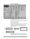
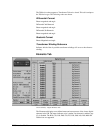
Current Transformers (CT)
Primary: indicates the current rating of the CT primary.
Secondary: indicates the output current of the CT secondary, either 1A or 5A.
Displays "N/A" if the Order Code indicates no CT is installed in the affected
location.
Voltage Transformers (VT)
Secondary: indicates the output voltage of the VT.
Ratio: the turns ratio of the VT.