


PMCS Interface Toolkit Features of GE Large Faceplate Wizards • 85
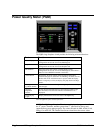
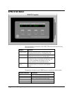
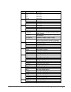
Page Text Displayed Description
1 Vln A Units in Volts
Vln B Units in Volts.
Vln C Units in Volts.
Vln Avg. Units in Volts.
2 Vll ab Units in Volts.
Vll bc Units in Volts.
Vll ca Units in Volts.
Vll avg Units in Volts.
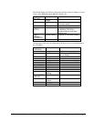
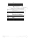
3 Ia Units in Amps
Ib Units in Amps
Ic Units in Amps.
Iavg Units in Amps
4 V unbalance % deviation from Vln or Vll avg for the phase having the
greatest unbalance
I unbalance % deviation from I avg for the phase having the greatest
current unbalance
Line Frequency Fundamental Frequency of Phase A voltage.
Phase Reversal Boolean register indicating if there is a phase reversal.
When the voltage phases do not rotate in the sequence
specified by the phase order setup, this register is ON.
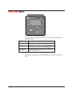
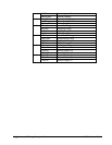
5 kW a Real Power for phase a
kW b Real Power for phase b
kW c Real Power for phase c
kW total Total Real Power
6 kVAR a Reactive power for phase a
kVAR b Reactive power for phase b
kVAR c Reactive power for phase c
kVAR total Total Reactive power
7 kVA a Apparent Power for phase A
kVA b Apparent Power for phase B
kVA c Apparent Power for phase C
kVA total Total Apparent Power
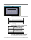
8 PF signed a Signed Power Factor Phase A
PF signed b Signed Power Factor Phase B
PF signed c Signed Power Factor Phase C
PF sign Total Signed Power Factor Total
9 kW SD Real Power Sliding Demand
kW PD Real Power Predicted Demand
kVAR SD Reactive Power Sliding Demand
kVAR PD Reactive Power Predicted Demand
10 kVA SD Apparent Power Sliding Demand
kVA PD Apparent Power Predicted Demand
Vln avg MAX Maximum Average Voltage
I avg MAX Maximum Average Current
11 kW MAX Maximum Real Power
kVAR MAX Maximum Reactive Power