


60 • Sample Application PMCS Interface Toolkit
navigate the screens, we’ll create extra buttons on the bottom of the Faceplate and
Tabular screens that will jump back to the Panelboard screen.
With our plan in hand, and after completing the installation procedures described in
Chapter 1, we’re ready to begin development.
Launch CIMPLICITY and create a new project file as described in Chapter 2. Use
the PMCS PowerBuilder to create 5 new devices in your project:
PQM Device type = MLPQM
Trip1 Device type = EMVTC
Trip2 Device type = EMVTC
Trip3 Device type = EMVTC
Trip4 Device type = EMVTC
Click the “Generate Screens” button and let PowerBuilder create the device screens.
When PowerBuilder is finished your project contains three windows:
MainMenu.cim – contains all the small faceplates for the project
wzEMVTC-D.cim – Trip Unit Faceplate/Tabular wizard
wzMLPQM.cim – PQM Faceplate/Tabular wizard
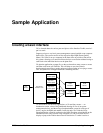
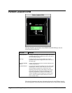
Rename the "MainMenu.cim" screen "Panelboard". Add a new window called "Main
Screen", and use the CIMPLICITY tools to sketch a floorplan of the facility, as
shown below:
In the Manufacturing Floor area, create a button labeled "Click here to begin…," and
give it an animation link to the screen named Panelboard.
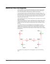
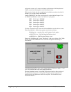
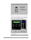
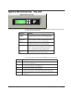
Open the Panelboard screen. Use the PMCS Elevation wizards to add a mock-up of
the panelboard, then move the existing Small Faceplate wizards to populate the
panelboard with our PQM meter and the four trip units. The Panelboard screen
should look like this: