


88 • Features of GE Large Faceplate Wizards PMCS Interface Toolkit
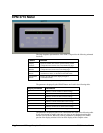
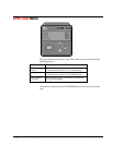
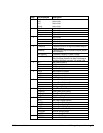
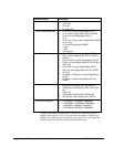
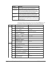
Screen Selected Description
1 - Total Power
• KW Total
• KVAR Total
• KVA Total
• PF Signed Total
2 - Three-Phase Measurements
• Vln a; Vln b: n/a when Voltage Mode is DELTA
• Vln c: n/a when Voltage Mode is DELTA or SINGLE
• Vln Avg: n/a when Voltage Mode is DELTA
• Vll ab
•
Vll bc; Vll ca; Vll avg: n/a when Voltage Mode is SINGLE
• Ia, Ib, I4, Iavg
• Ic: n/a when Voltage Mode is SINGLE
• V unbal
• I unbal
• Line Frequency
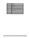
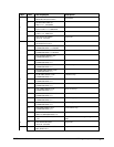
3 - Per-Phase Power
• KW a; KW b: n/a when Voltage Mode is DELTA
• KW c: n/a when Voltage Mode is DELTA or SINGLE
• KW Total
• KVAR a; KVAR b: n/a when Voltage Mode is DELTA
• KVAR c: n/a when Voltage Mode is DELTA or SINGLE
• KVAR Total
• KVA a; KVA b: n/a when Voltage Mode is DELTA
• KVA c: n/a when Voltage Mode is DELTA or SINGLE
• KVA Total
• PF Signed a; PF Signed b: n/a when Voltage Mode is
DELTA
• PF Signed c: n/a when Voltage Mode is DELTA or
SINGLE
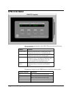
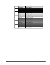
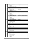
4 - Energy
• KWh Import; KWh Export; KWh Total; KWh Net
• KVARh Import; KVARh Export; KVARh Total; KVARh
Net
• KVAh Total
• KW Total Min; KVAR Total Min; KVA Total Min
• KW Total Max; KVAR Total Max; KVA Total Max
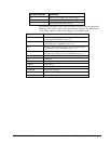
5 - Symmetrical Components
• I ZeroSeqMag; I PosSeqMag; I NegSeqMag
• V ZeroSeqMag; V PosSeqMag; V NegSeqMag
• I ZeroSeqPhs; I PosSeqPhs; I NegSeqPhs
• V ZeroSeqPhs; V PosSeqPhs; V NegSeqPhs
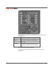
**NOTE: If the Sliding Demand Reset is initiated, or a SWD setup register is
changed, SWD values are “N/A” in the meter until the number of sub-intervals
specified in the #sub intervals setup register have expired. The 3-D faceplate and
Tabular wizard will display 0 for these values during this state.