


PMCS Interface Toolkit Configuring and Using PMCS Wizards • 39
Circuit Breaker One-Line Wizards
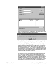
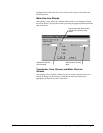
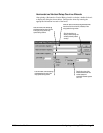
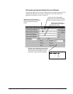
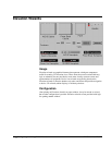
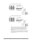
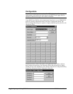
After placing a Horizontal or Vertical Circuit Breaker wizard in a window, double-
click on it to display the dialog box shown below. Configure the wizard by entering
the appropriate information into each of the boxes.
Enter text to display next to the breaker graphic
during runtime (optional).
Enter the name of the discrete tag that determines
the color of the line to the right (or top) of the breaker
symbol during runtime.
Enter the name of the discrete tag that
determines the color of the line to the left (or
bottom) of the breaker symbol during runtime.
Specify the colors of the wizard
elements and status text for the
breaker states during runtime. See
the table below for default status/
color mappings.
Enter the name of the analog tag
that determines the color of the
circuit breaker symbol, the state of
the breaker, and the status text
displayed next to the breaker icon
during runtime.
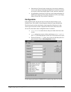
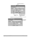
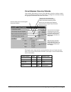
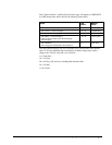
The breaker status values and the associated default colors are listed in the table
below. Error status indicates that the breaker status inputs create an indeterminate
state for the breaker.
Breaker Status Value Text Default Color
Open 1 OPN Green
Closed 3 CLD Red
Drawn Out 5 OUT Green
Tripped 7 TRP Yellow
Error 9 ERR Flashing Red
Breaker status values & display colors.