


Troubleshooting 64
The Harmony 802.11a CardBus Card includes two integral omnidirectional antennas.
Note that the coverage footprint of the CardBus Card’s antennas will vary depending
on the laptop’s design and the location of the CardBus slot in the computer.
The Harmony 802.11a PCI Card includes two integral omnidirectional antennas: one
antenna is attached directly to the card and the other is connected by a cable.
Proper antenna placement can help improve range. Here are some guidelines:
• Try to keep the adapter’s antennas free of obstructions (particularly metal
objects) and do not place a sheet of metal (like a filing cabinet) between two
antennas.
• Use the Harmony Utility to evaluate the signal strength and link quality between
802.11a devices.
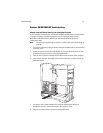
• For PCI Card users: At the point where the Ethernet cable connects to the PCI
Card, position the cable so that it is perpendicular to the card’s attached antenna
until the cable is at least two or three inches away from the card’s bracket.
Note: See the
Harmony 802.11a Access Point User’s Guide
for additional
suggestions.
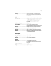
CardBus Card LED Indicators
The Harmony 802.11a CardBus Card includes two green LED indicators on the top of
the card near the antenna.
These LEDs display the following behavior:
• Both LEDs are off when the adapter is not receiving power or when the Harmony
driver is not installed.
• The LEDs blink in an alternating pattern when the adapter is searching for an
Access Point (in Infrastructure mode) or Ad Hoc network (in Ad Hoc mode).
• The LEDs blink in unison every second when the adapter has associated with an
Access Point or joined an Ad Hoc network.
• When there is network activity, the LEDs blink at a faster rate; the LEDs will blink
in unison more often as the adapter’s Send or Receive Rate increases.