


Removal and Installation
8-101
HP DesignJet 5000 Series Printers Service Manual
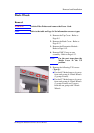
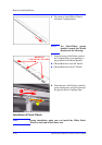
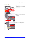
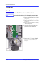
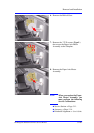
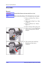
6. Remove the Helical Gear.
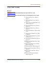
7. Remove the 3 T-20 screws (Type L)
that secure the Paper-Axis Motor
Assembly to the Sideplate.
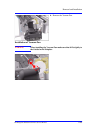
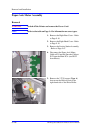
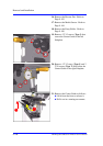
8. Remove the Paper-Axis Motor
Assembly.
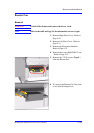
NOTE When you replace the Paper-
Axis Motor Assembly you
must perform the following
Service Calibrations:
n Service Station ⇒ Page 5-11.
n Accuracy ⇒ Page 5-14.
n Printhead Alignment ⇒ User’s Guide.