


Removal and replacement procedures 97
Device number Connector
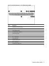
System Fan 4 J70 on the system board
System Fan 5 J68 on the system board
System Fan 6 J67 on the system board
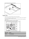
System fans 1 to 4 are for the memory modules and processors, while system fan 5 to 6 are for the PCI slots
and system chipsets.
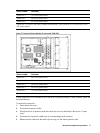
Figure 97 System Fan Device Number of system with 130W CPU
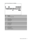
Device number Connector
System Fan 1 J63 on the system board
System Fan 2 J71 on the system board
System Fan 3 J68 on the system board
System Fan 4 J62 on the system board
System Fan 5 J70 on the system board
System Fan 6 J67 on the system board
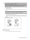
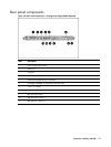
A new system fan can be installed to allow the server to operate properly in case a default system fan
becomes defective.
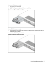
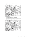
To remove the system fan:
1. Power down the server.
2. Disconnect the power cord(s).
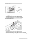
3. Unlock the server if necessary and remove the top cover as described in the section “System
cover”.
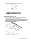
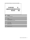
4. Disconnect the system fan cable from its corresponding board connector.
5. Release the fan cable from the cable clip securing it to the chassis partition wall.