


Removal and replacement procedures 59
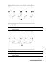
Item Description
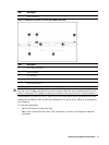
4 SATA connectors
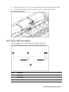
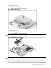
Figure 32 Backplane Connectors of Server with 8 HDD (solder side)
Item Description
1 PIC 2 PROG connector
2 Power connector
3 I2C connector
4 PIC 1 PROG connector
5 Mini SAS connectors
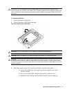
WARNING: Ensure that the system is powered off and all power sources have been disconnected
from the server. Voltages are present at various locations within the server whenever an AC power
source is connected. This voltage is present even when the main power switch is in the off position.
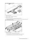
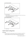
The backplanes for the servers with 2 HDDs and 4 HDDs and 8HDDs share the same removal and
replacement procedures. Here we take the backplane for the server with 4 HDDs as an example for
your reference.
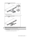
To remove the backplane:
1. Remove all drives out of the drive bays.
Refer to the “Optical disc drive bay” and “Hard drives” sections in this chapter for detailed
procedures.