


Removal and replacement procedures 39
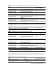
Table 8 Cable connections from the 460W/750W Hot-plug Power Supply (Optional)
Cable To Cable Designator
Switching power supply System board 24-pin power connector P1
Switching power supply System board 8-pin power connector P2
Switching power supply System board 4-pin power connector P3
Switching Power Supply Graph card power connector P4
Switching Power Supply 4/8 HDD hot-plug Backplane power
connector
P5
Switching power supply Optical disc drive CD
Switching Power Supply System board backplane power connector RPS
Switching power supply 2 HDD hot-plug Backplane power connector P10/P11
Switching power supply 4 Non hot-plug HDD P6,P7,P8,P9
NOTE: P6,P7,P8,P9,P10 and P11are extended connectors from P5, P4 are the extended 6-pin
connector from 10-pin P4 connector.of power supply.
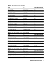
Table 9 Cable connections from the 500 W Non-hot-plug Power Supply
Cable To Cable Designator
Switching power supply System board 24-pin power connector P1
Switching power supply System board 8-pin power connector P2
Switching power supply System board 4-pin power connector P3
Switching Power Supply 4/8 HDD hot-plug Backplane power
connector
P7
Switching Power Supply Graph card power connector P4
Switching power supply Optical disc drive P5
Switching power supply 2 HDD hot-plug Backplane power connector P10
Switching power supply 4 Non hot-plug HDD P11,P12,P13,P14
NOTE: P10,P11,P12,P13,P14 are extended connectors from P7
The following tables provide the system board designators that various cables plug into. For more
detailed information about system board components, see “Figure 106 System Board Components”.
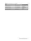
Table 10
Cable Connections from the System Board
Cable To System Board Designator
20-pin front panel connector Front panel J42
USB 0/1 connector Front panel USB 2.0 J56