


Removal and replacement procedures 64
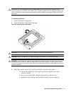
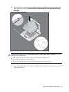
CAUTION: Do not over-tighten the spring-loaded screws to prevent them from breaking off. A
maximum torque of 6 inch-lb is set for each screw. Rotate the heat sink a few degrees to the left and
right to break the bonding of the thermal grease compound before removing the heat sink from the
processor.
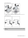
To remove the processor:
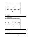
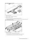
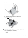
1. Open the processor locking lever.
2. Open the processor socket retaining bracket.
Figure 40 Opening the lever and bracket
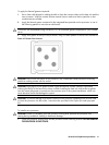
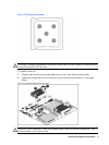
CAUTION: The pins of the socket are very fragile. Do not bend or damage them.
CAUTION: Place the processor on a static-dissipating work surface or in an anti-static bag.
CAUTION: To allow heat sink to draw as much heat as possible from the processor base, there must
be good contact between the heat sink base and the top of the processor. To ensure good contact,
you must first remove any residue of the old thermal compound with alcohol and apply new thermal
grease compound.
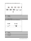
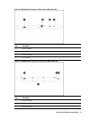
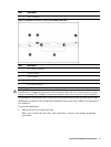
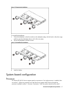
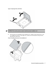
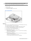
3. Using the processor removal tool, remove the processor from the system board.
a. Line up the processor tool, ensuring the locking lever graphic on the tool is
correctly oriented.
b. Press in on the plastic tabs, and then place the tool on the processor.
c. Release the tabs, and then carefully lift the processor and tool straight up.