


10
•
Installation
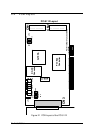
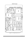
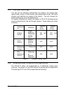
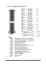
2.5 Jumper Settings
You can set the following configuration by jumpers: the analog input
signal mode, counter’s clock source, and analog output range. The card's
jumpers and switches are preset at the factory. You can change the
jumper settings for your own applications.
For system reliability and safety, the design of PCI-9112 still keeps some
board configurations to be set through jumpers. These setting are listed
as below.
Configurat
ion
Attributes
Jumpers
(PCI-
9112)
Jumpers
(cPCI-
9112)
Analog
Inputs
Single-
ended or
Differential
Analog
Input
JP1 and
JP5
JP1 and
JP4
Clock
Source
Internal
Clock or
External
Clock
JP2 JP2
D/A
Reference
Voltage
-10V or -5V JP3 JP3
D/A
Reference
Source
Internal
Reference
or
External
Reference
JP4 JP5
Table 2.1 Jumpers Listing Table
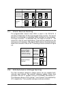
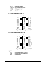
2.6 Analog Input Channel Configuration
The PCI-9112 offers 16 single-ended or 8 differential analog input
channels. The jumper JP1 and JP5 control the analog input configurations.
The settings of JP1 and JP5 are specified as following: