


12
•
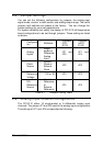
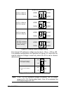
Installation
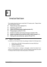
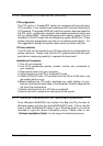
D/A CH1 is External
D/A CH2 is External
JP4(PCI-9112) JP5(cPCI-9112)
INTREF
ExtRef2ExtRef1
INTREF
D/A CH1 is Internal
D/A CH2 is Internal
(default setting)
D/A CH1 is Internal
D/A CH2 is External
D/A CH1 is External
D/A CH2 is Internal
INTREF
ExtRef2ExtRef1
INTREF
INTREF
ExtRef2ExtRef1
INTREF
INTREF
ExtRef2ExtRef1
INTREF
Figure 2.4 Analog Output Voltage Setting
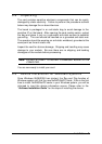
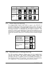
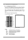
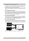
The internal A/D reference voltage can be set to –5V or –10V by JP3.
The possible configurations are specified as Figure 2.5. Note that the
internal reference voltage is used only when the JP4 is set to internal
reference only.
Reference Voltage is
-5V (default setting)
JP3
-10V
-5V
JP3
-10V
-5V
Reference Voltage is
-10V
Figure 2.5 Internal Reference Voltage Setting
Note : If the -10V D/A reference voltage is selected, the D/A output
range is 0V~10V. On the other hand, if the -5V is selected, the
D/A output range is 0V~5V.