


Installation
•
11
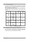
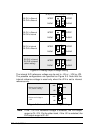
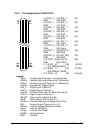
Differential
Input
Single-ended
(default setting)
JP5
SINGLE
DIFF
JP5
DIFF
JP1
DIFF
JP1
DIFF
DIFF
DIFF
JP1
DIFF
JP1
DIFF
JP4
JP4
PCI-9112 cPCI-9112
SINGLE
SINGLE SINGLE
SINGLE
SINGLE
SINGLE
SINGLE
Figure 2.2 Analog Input Mode Setting
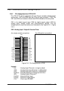
2.7 Clock Source Setting
The programmable interval timer 8254 is used in the PCI-9112. It
provides 3 independent 16-bit programmable down counters. The input of
counter 2 is connected to a precision 2MHz oscillator for internal pacer.
The input of counter 1 is cascaded from the output of counter 2. The
channel 0 is free for user's applications. There are two selections for the
clock source of channel 0 : the internal 2MHz clock or the external clock
signal from connector CN3 pin 35. The setting of clock is shown as Figure
2.3.
Internal Clock
Source: 2MHz
(
default setting)
External Clock
Source JP2
JP2
INTCLK
EXTCLK
INTCLK
EXTCLK
Figure 2.3 Timer's Clock Source Setting
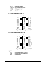
2.8 D/A Reference Voltage Setting
The D/A converter's reference voltage source can be supplied both
internally and external. The external reference voltage comes from
connector CN3 pin 31 (ExtRef1) and pin12 (ExtRef2), see section 3.1.
The reference source of D/A channel 1 and channel 2 are selected by
JP4, respectively. Their possible settings are shown as below: