


Installation
•
13
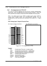
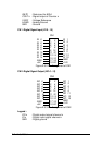
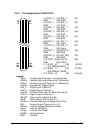
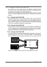
2.9 Connectors Pin Assignments
2.9.1 Pin Assignments of PCI-9112
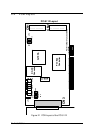
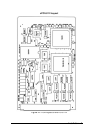
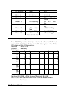
The PCI-9112 comes equipped with two 20-pin insulation displacement
connectors - CN1 and CN2 and one 37-pin D-type connector - CN3. The
CN1 and CN2 are located on board and CN3 located at the rear plate.
CN1 is for digital signal input, CN2 for digital signal output, CN3 for
analog input, analog output and timer/counter's signals. The pin
assignments for each connector are illustrated in the Figure 2.9.1~ Figure
2.9.3.
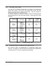
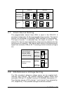
CN 3: Analog Input / Output & Counter/Timer
(for single-ended connection) (for differential connection)
AI2
1
2
3
4
5
6
7
8
9
10
11
12
13
14
15
16
17
18
19
21
22
23
24
25
26
27
28
29
30
20
31
32
33
34
35
36
37
AI3
AI10
AI9
AI8
AI1
AI0
AI6
AI7
AI5
AI4
AI13
AI14
AI12
AI11
AO1
A.GND
AI15
A.GND
A.GND
A.GND
V.REF
ExtRef2
ExtRef1
AO2
A.GND
+12V
D.GND
GATE0
GATE
COUT1
N/C
ExtCLK
N/C
+5V
ExtTrg
COUT0
CN3
Figure 2.9.1 Pin Assignments of CN3
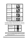
Legend :
AIn : Analog Input Channel n ( single-ended)
AIHn : Analog High Input Channel n ( differential)
AILn : Analog Low Input Channel n ( differential)
ExtRef n : External Reference Voltage for D/A CH n
AOn : Analog Output Channel n
ExtCLK : External Clock Input
ExtTrig : External Trigger Signal
CLK : Clock input for 8254