


Removal and Replacement Procedures
Maintenance and Service Guide 5–53
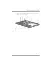
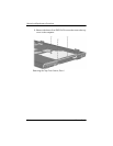
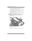
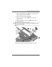
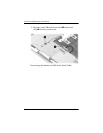
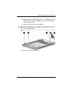
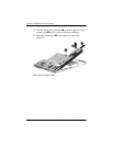
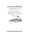
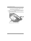
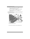
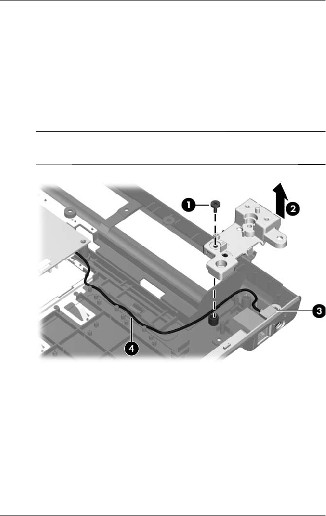
5. Remove the PM2.5×6.0 screw 1 that secures the display
hinge support to the base enclosure.
6. Remove the display hinge support 2.
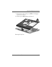
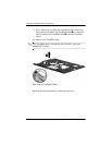
7. Remove the power connector 3 from the clip in the
base enclosure.
8. Remove the power connector cable 4 from the clips in
thebaseenclosure.
✎
The display hinge support is included in the Bracket Kit, spare
part number 407820-001.
Removing the Display Hinge Support and Power Connector