


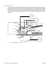

Removal and replacement strategy
This chapter describes how to remove, replace, and reassemble the major assemblies of the digital
sender. Replacement is generally the reverse of removal.
WARNING! Unplug the power cord from the power outlet (at the wall receptacle) before
attempting to service the digital sender. If you do not follow this warning, severe injury can result.
Certain functional checks during troubleshooting might require power to be supplied to the digital
sender. However, all power should be turned off and the product should be unplugged when you
remove any digital sender assemblies or components. Never operate or service the digital sender
when the protective cover is removed from the laser/scanner assembly. The reflected beams,
although invisible, can damage your eyes.
CAUTION: The product contains components that are sensitive to electrostatic discharge
(ESD). Always perform service work at an ESD-protected workstation. If an ESD-protected
workstation is not available, discharge body static by grasping the digital sender chassis before
touching an ESD-sensitive component. Ground the digital sender chassis before servicing the
digital sender.
NOTE: To identify the left side and right side of the digital sender, face the control panel.
Required tools
●
#1 Phillips screwdriver
●
#2 Phillips screwdriver
●
#2 Phillips screwdriver with a shaft diameter of 6 mm (0.25 inch) or less
●
Short #2 Phillips screwdriver shaft length of 76 mm (3.0 inches)
●
Right-angle #2 Phillips screwdriver
●
Small flat-blade screwdriver
●
Needle-nose pliers
●
ESD mat (if available; see the preceding ESD caution)
●
Penlight (optional)
●
Tape (optional)
CAUTION: A pozidriv screwdriver can damage screw heads on the product. Use a #2 Phillips
screwdriver.
Before performing service
●
If possible, go to the digital sender embedded Web server and print the configuration page.
36 Chapter 5 Removal and replacement ENWW