


HP OmniBook XE2 Removal and Replacement 2-1
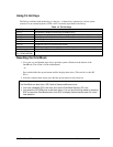
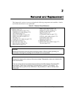
This chapter tells you how to remove and replace the following components and assemblies. A bullet
(
•) indicates that an item is user-replaceable.
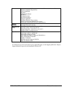
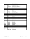
Table 2-1. Removal Cross-Reference
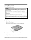
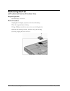
• Battery (page 2-3).
Bottom case (table on page 2-21).
CD-ROM drive (table on page 2-21).
CPU module (page 2-17)
Display bezel (table on page 2-21).
Display case (table on page2-21).
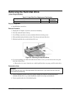
Fan (page 2-7).
Floppy disk drive (table on page 2-21).
• Foot (table on page 2-7).
• Hard disk drive (page 2-6).
Heatsink (table on page 2-21).
Hinge (table on page 2-21).
Hinge cover (table on page 2-21).
Inverter PCA (table on page 2-21).
LED PCA (table on page 2-21).
Keyboard (page 2-9).
LCD brackets (table on page 2-21).
LCD flex cable (table on page 2-21).
LCD module (page 2-21).
Motherboard (page 2-17).
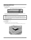
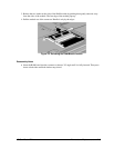
• RAM board (page 2-3).
• RAM module cover (table on page 2-7).
Top case (page 2-15).
Caution
Always provide proper grounding when performing repairs. Without proper grounding, an
electrostatic discharge may damage the OmniBook and its components.
Note
Reassembly steps are the reverse of the removal steps. Reassembly notes are included at the
end of each section.
There are some removal and replacement procedures that differ between Omnibook XE2
technologies. Refer to the Technology Code description in section 5.3 for details. The
Technology Code (e.g DD) will be referenced in the procedures in order to identify these
differences.