


Appendix A: Specifications
171
Information on Jumpers
The Information on Jumpers section provides an overview of how to change a jumper settings for any
board and provides the jumper block diagrams for the following boards:
• General Procedure to Change Jumper Settings
• Processor Baseboard
• Legacy I/O Board
• I/O Baseboard
• T-Docking Board
• SCSI Backplane Board
General Procedure to Change Jumper Settings
These general instructions describe how to change a jumper setting:
1. Observe all safety and ESD precautions.
2. Turn off all connected peripherals.
WARNING Make sure that the rack is anchored securely, so it will not tip when the server
chassis is extended.
Remove the power cords to ensure that the server is not under standby power.
3. Power down the server by pressing and holding the Power button on the Front Control Panel.
You may have to hold the Power button down for several seconds. Disconnect all AC power
cords to remove standby power from the server.
4. Expose the board on which the jumpers reside. For procedures that describe how to access
system boards, refer to Chapters 5 through 8.
5. Locate the configuration jumper blocks on the board.
6. Move jumper to pins specified for the desired setting.
7. Reinstall any boards or components that you had to remove in order to access the jumpers.
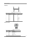
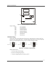
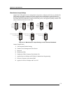
Processor Baseboard Jumpers
The jumper blocks on the Processor Baseboard allow you to route Joint Test Action Group (JTAG)
Test Data In (TDI) and Test Data Out (TDO) signals through different components on the Processor
Baseboard. Additionally, jumper blocks allow you to configure the host bus frequency, set the
processor frequency, and set other miscellaneous functions. To access these jumper blocks, expose
the top half of the Processor Baseboard by following the procedure in Chapter 6 “Installing an
Additional Processor”. Figure A-9 shows where the jumper blocks reside on the top half of the
Processor Baseboard.