


49
Chapter 3 Installing and Configuring
Accessory Boards
Introduction
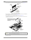
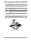
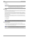
This section describes how to install accessory boards into the system board of the HP Server tc4100. The
system board provides up to six PCI slots (P1 through P6), two of which are 64-bit slots.
Tested PCI Boards
For a list of tested PCI boards, check for compatibility in Configuration Assistant on the Navigator CD-ROM
or look for the Hardware Tested Products list for the HP Server tc4100 under the Service and Support topic for
the specific NOS used in the Server at HP’s web site:
http://www.hp.com
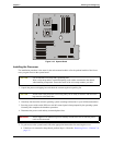
Tools Required
The following tools are required for installation or removal of the accessories boards in the HP Server tc4100:
• An antistatic service kit (3M™ 8501/8502/8503 or equivalent). This kit includes a static-dissipating work
surface, a chassis clip lead, and a wrist strap with ground lead.
• Torx 15 screw driver.
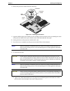
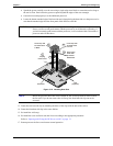
HP Server Remote Management Card
The HP Server Remote Management Card has to be installed in slot 6. There is a 50-pin connector/cable that
should connect the HP Server Remote Management Card and the system board.
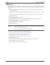
Boot Priority
This section details the HP Server tc4100’s boot order by highest to lowest priority. The Server’s boot order
(BIOS search order for a boot drive) should be considered when selecting a slot on the system board. This is
especially important if you are installing a SCSI disk controller board. The disk controller’s boot priority is set
by the board’s slot location.
The on-board SCSI consists of two channels, A and B. Channel B is typically used to control the Hot Swap
SCSI drives. Channel A is typically used to control the internal non-hot swap SCSI drives. On each SCSI
channel, the system scans for a boot device starting at device ID 0 and works up from there.
By default the Server searches for boot devices in this order:
1. IDE CD-ROM drive
2. Flexible disk drive
3. SCSI A bus (typically the non-Hot Swap internal SCSI devices)
4. SCSI B bus (typically the Hot Swap Mass Storage Cage)
5. PCI slot 6
6. PCI slot 5
7. PCI slot 4
8. PCI slot 3
CAUTION Some accessory board outputs may exceed U.S. National Electrical code (NFPA 70)
Class 2 or limited power source limits and must use appropriate interconnecting cabling
in accordance with the National Electrical Code. (All Hewlett Packard boards comply
with Class 2.)