


122 Chapter 4
Field Replaceable Units
FRU Removal and Replacement
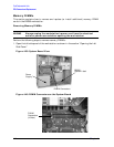
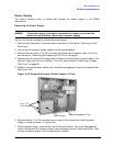
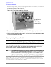
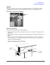
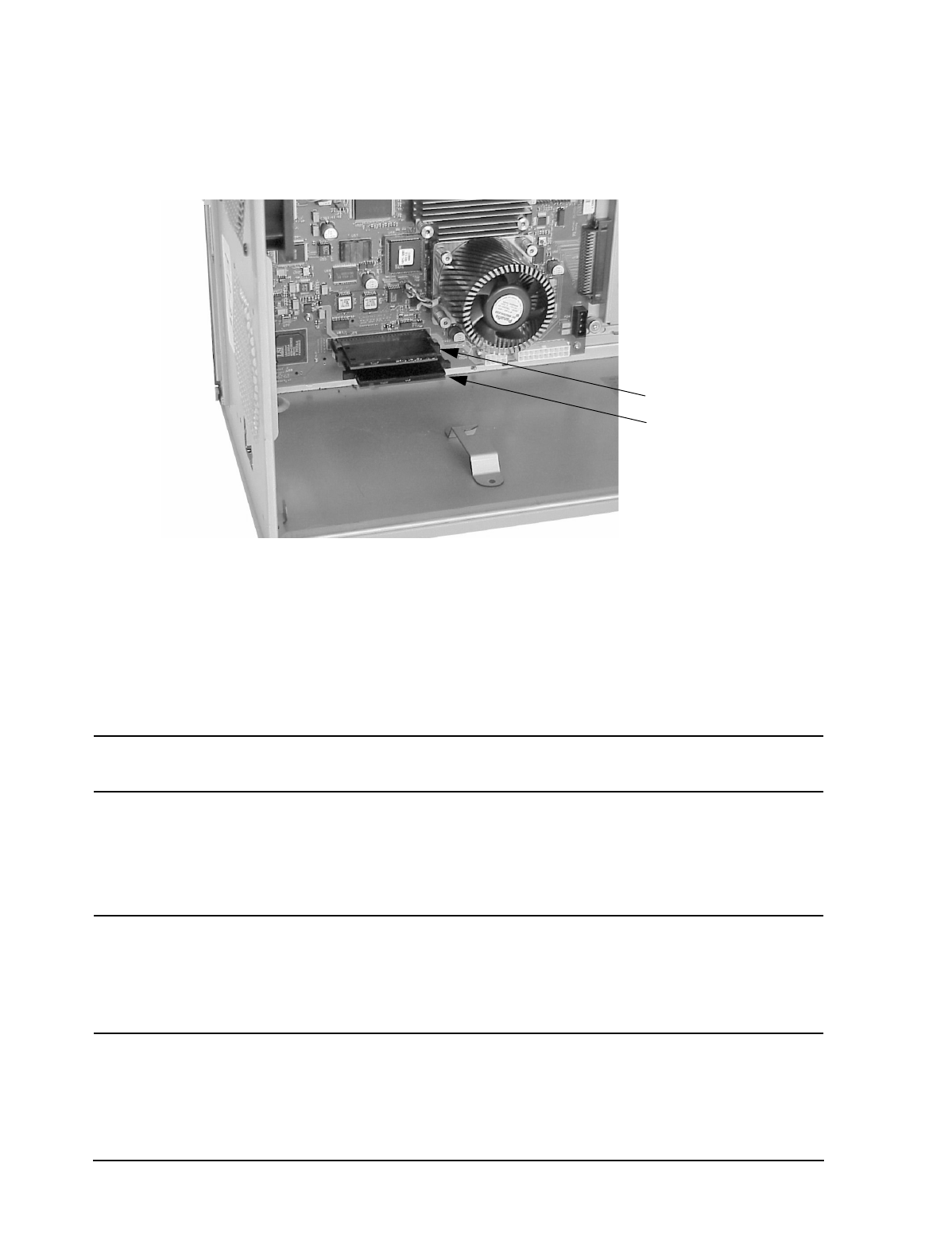
As shown in Figure 4-48, the top voltage regulator module is the master, and the bottom
one nearest the chassis floor is the slave.
Figure 4-48. The Voltage Regulator Modules
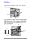
4. Press down on the ejector tabs located on each side of the voltage regulator module
(master or slave) to release it from the system board connector.
5. Grasp the voltage regulator module (master or slave) firmly and pull outward to release
it from the system board connector.
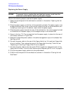
Replacing a Voltage Regulator Module
WARNING
To prevent injury, unplug the workstation’s power cord from the
electrical outlet before replacing a voltage regulator module.
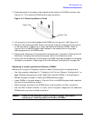
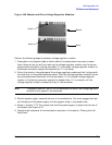
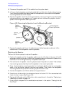
Before replacing a voltage regulator module, ensure that it is the correct one (master or
slave) for insertion into the correct connector on the system board. See Figure 4-49 to
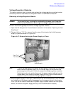
identify the two different voltage regulator modules (master and slave).
NOTE
The master and the slave voltage regulator modules differ in the placement of
the notch in their gold edge connectors, as shown in Figure 4-49. This notch
fits the notch-key of the system board’s connector into which each voltage
regulator module (master or slave) fits. The notches and notch-keys prevent
you from installing a voltage regulator module into the wrong connector.
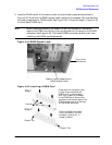
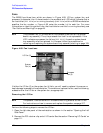
Refer to Figure 4-48 for the correct system board connector (the top connector for the
master, or the bottom connector nearest the chassis floor for the slave) in which to insert
the voltage regulator module you need to replace.
Voltage Regulator
Modules:
Master (Top)
Slave (Bottom)