


113
www.honeywell.com/sensing
LINEAR AND ROTARY POSITION
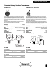
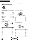
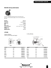
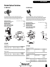
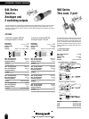
S-510 Series
The S-510 Series consists of a gallum arsenide IRED and silicon
phototransitor mounted in a small injection-molded housing. An IR-opaque
housing is offered for applications where high levels of ambient infrared
radiation may be present and an IR-transparent housing for applications
requiring protection from dust and dirt in the apertures. This series is also
available with 305,0 mm (12.0 in) minimum length flexible wire leads.
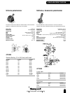
Operating temperature: -40 °C to 85 °C (-40 °F to 185 °F)
IRED continuous forward current: 50 mA
IRED peak forward current: 3 A
IRED reverse voltage: 3 V
IRED power dissipation: 100 mW
Sensor collector-emitter voltage: 30 V
Sensor emitter-collector voltage: 5 V
Sensor power dissipation: 100 mW
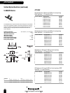
OPTIONS
IR-opaque housing
TERMINATION ELECTRICAL SELECTION REFERENCE
PC Board mount A S-510-A
Wire A S-510-AW
PC Board mount B S-510-B
Wire B S-510-BW
IR-transparent housing
TERMINATION ELECTRICAL SELECTION REFERENCE
PC Board mount A S-511-A
Wire A S-511-AW
PC Board mount B S-511-B
Wire B S-511-BW
PARAMETER I
L
V
CE(sat)
A 0.5 mA @ I
F
= 20 mA and V
CE
= 5 V 0.4 V max @ I
F
= 20 mA and I
C
= 0.25 mA
1.0 mA @ I
F
= 35 mA and V
CE
= 5V 0.4 V max @ I
F
= 35 mA and I
C
= 0.50 mA
B 1.0 mA @ I
F
= 20 mA and V
CE
= 5 V 0.4 V max @ I
F
= 20 mA and I
C
= 0.50 mA
2.0 mA @ I
F
= 35 mA and V
CE
= 5V 0.4 V max @ I
F
= 35 mA and I
C
= 1.0 mA
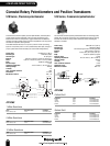
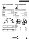
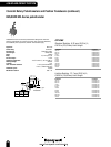
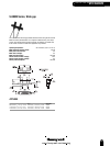
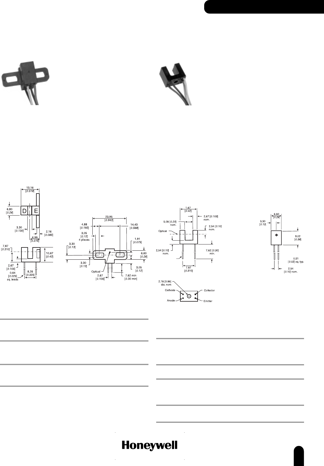
S-180 Series
The S-180 Series consists of a gallum arsenide IRED and silicon
phototransistor mounted in a rigid one-piece polycarbonate housing. All
electrical options are available with either PCB mount or 457,0 mm
(18.0 in) minimum length wire termination (26 AWG type UL 1429)
Operating temperature: -40 °C to 85 °C (-40 °F to 185 °F)
IRED continuous forward current: 50 mA
IRED peak forward current: 3 A
IRED reverse voltage: 3 V
IRED power dissipation: 100 mW
Sensor collector-emitter voltage: 30 V
Sensor emitter-collector voltage: 5 V
Sensor power dissipation: 100 mW
OPTIONS
PCB Mount
V
CE(sat)
I
L
REFERENCE
0.4 V max @ I
F
= 20 mA, I
C
= 0.4 mA 0.5 mA min @ I
F
= 20 mA and V
CE
= 5 V S-180-A55
0.4 V max @ I
F
= 10 mA, I
C
= 0.8 mA 1.0 mA min @ I
F
= 10 mA and V
CE
= 5 V S-180-B55
0.4 V max @ I
F
= 20 mA, I
C
= 2.0 mA 2.0 mA min @ I
F
= 20 mA and V
CE
= 5 V S-180-C55
Wire Leads
V
CE(sat)
I
L
REFERENCE
0.4 V max @ I
F
= 20 mA, I
C
= 0.4 mA 0.5 mA min @ I
F
= 20 mA and V
CE
= 5 V S-180-A55W
0.4 V max @ I
F
= 10 mA, I
C
= 0.8 mA 1.0 mA min @ I
F
= 10 mA and V
CE
= 5 V S-180-B55W
0.4 V max @ I
F
= 20 mA, I
C
= 2.0 mA 2.0 mA min @ I
F
= 20 mA and V
CE
= 5 V S-180-C55W
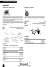
Slotted Optical Switches
OPTO SENSORS