


6
www.honeywell.com/sensing
LIMIT SWITCHES
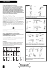
Proper application of limit switches
The following are guidelines for the correct application of Limit Switches.
Never use the Limit Switch as a physical end stop. Mechanical damage or
incorrect operation may occur if this is done. Always ensure that the
mechanical actuator is protected from excessive mechanical shock. Never
release the actuator suddenly - gradual actuation and release will ensure that
stress on the mechanics of the switch is kept to a minimum. This has the
added benefit that the switch life will be improved. The diagrams illustrate how
to actuate your limit switch for optimum performance.
Standards and Electrical rating
IEC/EN 60947-1 explains the general rules relating to Low Voltage switchgear
and controlgear. The purpose of this standard is to harmonize as much as
possible the product performance and test requirements for equipment where
the rated voltage does not exceed 1,000 Vac or 1,500 Vdc.
IEC 60947-5-1 is part 5 of the general rules which relates to Control-circuit
devices and switching elements, where rated voltage does not exceed 1,000
Vac or 600 Vdc. There are special requirements for control switches with
positive opening operation. These switches are marked on the outside with
this symbol:
The Contact Element form defines the configuration and number of contacts
within the switch.
Form Za – both contact elements have the same polarity
Form Zb – the two contact elements are electrically separated.
The Utilization Category defines the type of current carried – ac or dc – and
the typical application where the switch is used.
The contact rating Designation relates to the Utilization Categories and defines
the conventional thermal current Ith (a) rated operational current Ie (A) at
rated operational voltages Ue and the VA rating.
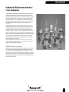
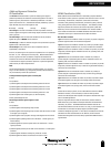
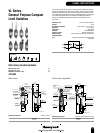
Actuators
A range of actuators is available for limit switches. Illustrations of actuator
types available from this catalogue are shown at the beginning of each
product family. Other actuators may be available - for more information
please contact your local Honeywell office.
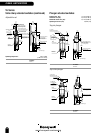
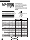
For limit switches with pushrod actuators, the actuating force should be applied as
nearly as possible in line with the pushrod axis.
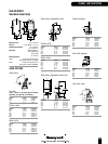
Cam or dog arrangements should be such that the actuator is not suddently released
to snap back freely.
Operating mechanisms for limit switches shoud be so designed that, under any
operating or emergency conditions, the limit switch is not operated beyond its
overtravel limit position. A limit switch should not be used as a mechanical stop.
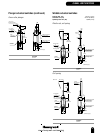
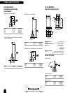
For limit switches with lever actuators, the actuating force should be applied as
nearly perpendicular to the lever as practical and perpendicular to the shaft axis
about which the lever rotates.
WRONG WRONG
RIGHT FIXED STOP
RIGHT
WRONG WRONG
RIGHT RIGHT
over-riding
cam
over-riding
cam
WRONG WRONG
RIGHT RIGHT
free position
free position
interference
end of
overtravel
operated
position
end of
overtravel
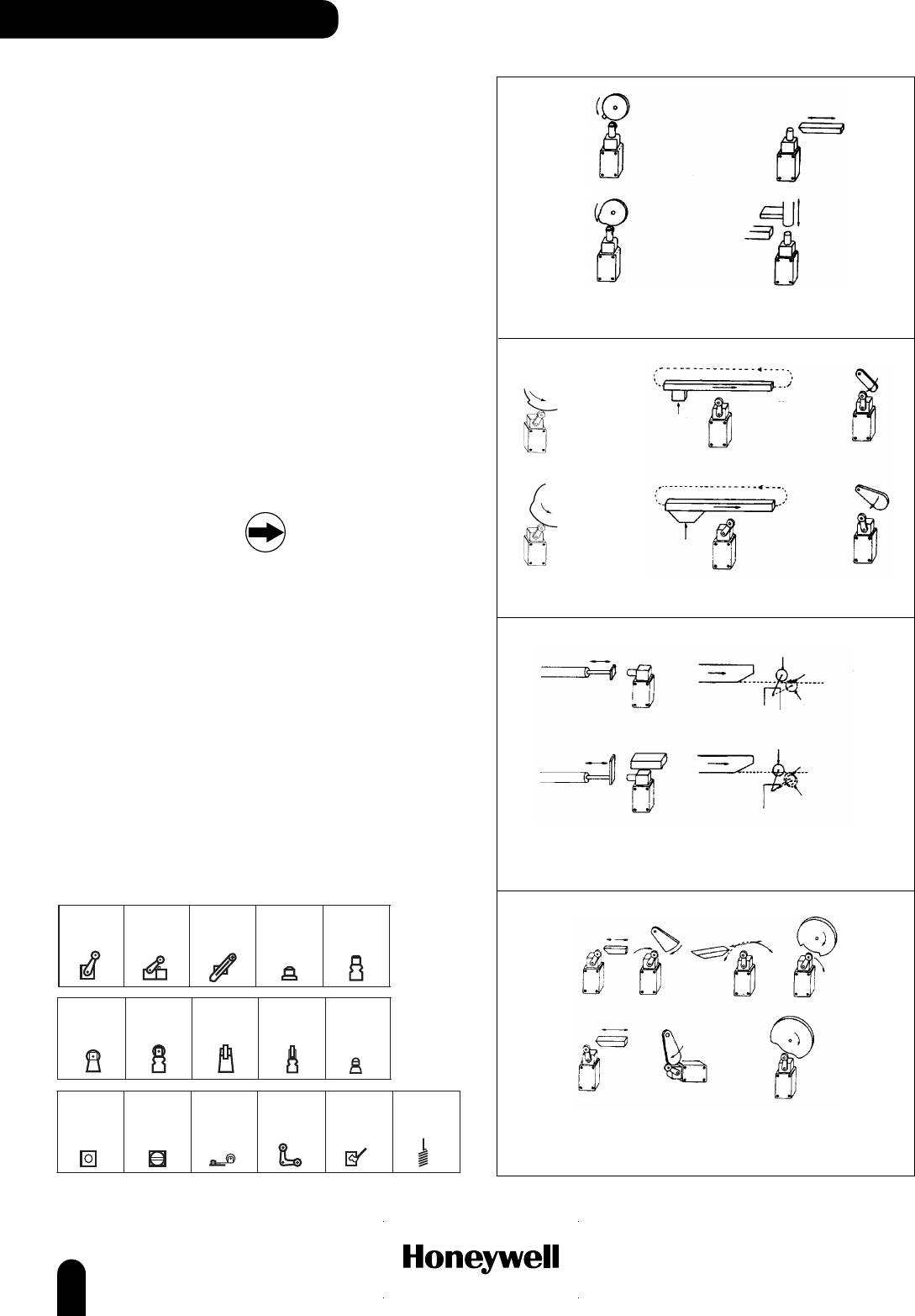
WRONG
RIGHT
over-riding
non-over-riding
Roller lever
Top roller
lever
Adjustable
roller lever
Top pin
plunger
Top pin
plunger,
boot seal
Top roller
plunger
Top roller
plunger,
boot seal
Top roller
plunger,
perpendicular
Top roller
plunger,
perpendicular,
boot seal
Ball bearing
plunger
Side
roller plunger
Side
pin plunger
Roller lever
Yoke lever
Rod lever
Wobble head