


FUNCTIONAL DESCRIPTION
E. MODEM
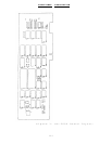
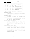
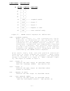
CONTROL REGISTER
+------+
D7 | 0 |
+------+
D6 | 0 |
+------+
D5 | 0 |
+------+
D4 | LOOP |----- Loopback enable
+------+
D3 | OUT2 |----- Output 2
+------+
D2 | OUT1 |----- Output 1
+------+
D1 | RTS |----- Request to send
+------+
D0 | DTR |----- Data terminal ready
+------+
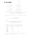
Figure 11. MODEM control register bit definitions.
LOOP - Loopback Enable:
When set (logic 1), the transmitter shift
register is connected to the receiver shift
register and the MODEM control inputs are
connected to the MODEM control outputs. All
characters transmitted are immediately received
to verify transmit and receive data paths.
Transmit and receive interrupts still operate
normally but MODEM control interrupts are now
controlled by the MODEM control register.
Bits OUT2, OUT1, RTS, and DTR perform identical
functions on their respective outputs. When these
bits are set (logic 1) in the register, the associated
output is forced to a logic 0. When cleared (logic
0), the output is forced to logic 1.
OUT2 - Output 2:
Controls the OUT2 output as described above.
Used for interrupt enable. See section VII.
OUT1 - Output 1:
Controls the OUT1 output as described above.
Unused on DS-2000.
RTS - Request To Send:
Controls the RTS output as described above.
DTR - Data Terminal Ready:
Controls the DTR output as described above.
Used for half-duplex control. See section IX.
iii