EX
TERNAL CONNECTIONS
X. EXTERNAL CONNECTIONS
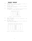
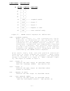
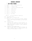
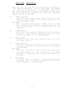
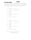
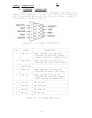
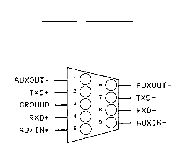
Connections to peripheral equipment are made via a
female D-9 connector. A pin-out of the D-9 connector
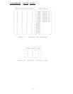
and a detailed description of each output signal is
illustrated in figures 24 and 25.
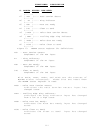
Figure 24. D-9 output configuration.
+-----+------------+----------------------------------+
| PIN | SIGNAL | DESCRIPTION |
+-----+------------+----------------------------------+
| 1 | AUX OUT+ | When combined with AUX OUT-, |
| | | provides the auxiliary channel |
| | | output defined by jumpers J2/J3. |
+-----+------------+----------------------------------+
| 2 | DATA OUT+ | When combined with DATA OUT-, |
| | | provides the serial data output. |
+-----+------------+----------------------------------+
| 3 | SIGNAL GND | |
+-----+------------+----------------------------------+
| 4 | DATA IN+ | When combined with DATA IN-, |
| | | provides the serial data input. |
+-----+------------+----------------------------------+
| 5 | AUX IN+ | When combined with AUX IN-, |
| | | provides the auxiliary channel |
| | | input defined by jumpers J2/J3. |
+-----+------------+----------------------------------+
| 6 | AUX OUT- | See AUX OUT+ |
+-----+------------+----------------------------------+
| 7 | DATA OUT- | See DATA OUT+ |
+-----+------------+----------------------------------+
| 8 | DATA IN- | See DATA IN+ |
+-----+------------+----------------------------------+
| 9 | AUX IN- | See AUX IN+ |
+-----+------------+----------------------------------+
Figure 25. D-9 signal definitions.
iii


