


OUT
PUT CONFIGURATIONS
IX. OUTPUT CONFIGURATIONS
Two sets of jumpers are implemented on the DS-2000
to control the auxiliary driver/receiver set. Jumpers J2
and J3 perform identical functions on channels 1 and 2
respectively.
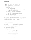
The function of J2 and J3 is to control the source
of the data exchanged on the auxiliary communication
lines. The output sources are request to send (RTS),
transmit clock (XCLK), and the auxiliary input (AUX IN).
The inputs are clear to send (CTS) and receive clock
(RCLK).
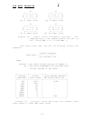
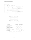
Transmission of RTS, when combined with reception of
clear to send (CTS), allows for handshaking between the
16550 and a peripheral device. RTS is transmitted by
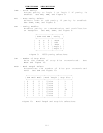
connecting pins 5 and 6 of the jumper block (figure 21).
CTS is received by connecting pins 1 and 2 (figure 21).
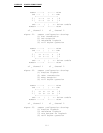
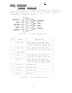
The RTS/CTS handshake can be defeated by looping the RTS
output back to the CTS input. This is accomplished by
connecting pins 1 and 5 of the jumper block (figures 22
and 23).
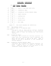
RCLK is the input to the 16550 which controls the
shift rate for the receiver portion of the chip.
Generally this input is provided by connecting it to the
XCLK output. This is performed by connecting pins 3 and
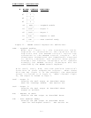
7 of the jumper block (figures 21 and 23). RCLK may be
received from an external source by connecting pins 2 and
3 (figure 22).
Transmission of XCLK can be used to help synchronize
communications with a peripheral or to provide a shift
clock for a receiver. Transmission of XCLK is
accomplished by connecting pins 6 and 7 of the jumper
block (figure 22).
AUX IN is the auxiliary input from a peripheral
device. Connecting AUX IN to AUX OUT provides a loopback
mode of operation. That is, whatever is transmitted by
the peripheral will be fed back to the peripheral. AUX
IN/ AUX OUT loopback is implemented by connecting pins 2
and 6 of the jumper (figure 23).
iii