


LIST OF FIGURES
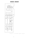
Figure 1. DS-2000 board layout . . . . . . . . . 2
Figure 2. 16550 internal registers . . . . . . . 3
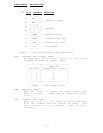
Figure 3. Interrupt enable register . . . . . . 4
Figure 4. Interrupt identification register . . 5
Figure 5. Interrupt source identification . . . 6
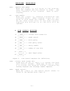
Figure 6. FIFO control register . . . . . . . . 7
Figure 7. FIFO receiver trigger levels . . . . . 7
Figure 8. Line control register . . . . . . . . 8
Figure 9. Parity options . . . . . . . . . . . . 9
Figure 10. Word length and stop bit options . . . 9
Figure 11. MODEM control register . . . . . . . . 10
Figure 12. Line status register . . . . . . . . . 11
Figure 13. MODEM status register . . . . . . . . 13
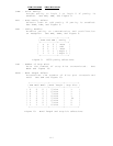
Figure 14. Input clock frequency options . . . . 15
Figure 15. Divisor latch options . . . . . . . . 15
Figure 16. POS implementation . . . . . . . . . . 17
Figure 17. Base address locations . . . . . . . . 18
Figure 18. Interrupt request levels . . . . . . . 18
Figure 19. Output control block diagram . . . . . 21
Figure 20. J2/J3 layout and settings . . . . . . 21
Figure 21. Auxiliary channel configuration
(handshake mode) . . . . . . . . . 22
Figure 22. Auxiliary channel configuration
(external clock mode) . . . . . . . 22
Figure 23. Auxiliary channel configuration
(loopback mode) . . . . . . . . . . 22
Figure 24. Output connections . . . . . . . . . . 23
Figure 25. Output signal definitions . . . . . . 23
iii