


EM78P447N
8-Bit Microcontroller with OTP ROM
22 •
Product Specification (V1.1) 03.30.2005
(This specification is subject to change without further notice)
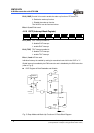
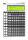
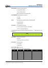
Voltage
Detector
Power-on
Reset
WDTE
Setup Time
VDD
DQ
CLK
CLR
CLK
RESET
WDT Timeout
WDT
/RESET
Oscillator
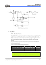
Fig. 8 Controller Reset Block Diagram
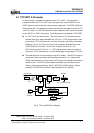
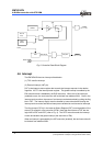
4.6 Interrupt
The EM78P447N has two interrupts listed below:
(1) TCC overflow interrupt
(2) External interrupt (/INT pin).
R3F is the interrupt status register that records the interrupt requests in the relative
flags/bits. IOCF is the interrupt mask register. The global interrupt is enabled by the
ENI instruction and is disabled by the DISI instruction. When one of the interrupts
(enabled) occurs, the next instruction will be fetched from address 001H. Once in the
interrupt service routine, the source of an interrupt can be determined by polling the flag
bits in R3F. The interrupt flag bit must be cleared by instructions before leaving the
interrupt service routine and before interrupts are enabled to avoid recursive interrupts.
The flag (except ICIF bit) in the Interrupt Status Register (R3F) is set regardless of the
status of its mask bit or the execution of ENI. Note that the outcome of R3F are the
logic AND of R3F and IOCF (refer to Fig. 9). The RETI instruction ends the interrupt
routine and enables the global interrupt (the execution of ENI).
When an interrupt is generated by the INT instruction (enabled), the next instruction will
be fetched from address 002H.