


EM78P447N
8-Bit Microcontroller with OTP ROM
24 •
Product Specification (V1.1) 03.30.2005
(This specification is subject to change without further notice)
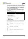
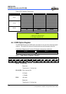
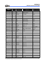
Table 11 The Summary of Maximum Operating Speeds
Conditions VDD Fxt max.(MHz)
2.3 4.0
3.0 8.0
Two cycles with two clocks
5.0 20.0
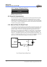
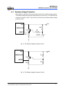
4.7.2 Crystal Oscillator/Ceramic Resonators(XTAL)
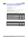
EM78P447N can be driven by an external clock signal through the OSCI pin as shown
in Fig. 10 below.
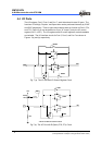
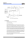
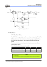
In most applications, Pin OSCI and Pin OSCO can be connected with a crystal or
ceramic resonator to generate oscillation. Fig. 12 depicts such circuit. The same thing
applies whether it is in the HXT mode or in the LXT mode. Table 12 provides the
recommended values of C1 and C2. Since each resonator has its own attribute, user
should refer to its specification for appropriate values of C1 and C2. RS. A serial
resistor may be necessary for AT strip cut crystal or low frequency mode.
OSCI
OSCO
EM78P447S
Ext. Clock
Fig. 10 Crystal/Resonator Circuit
OSCI
OSCO
EM78P447S
C1
C2
XTAL
RS
Fig. 11 Crystal/Resonator Circuit