


56 IBM System p5 520 and 520Q Technical Overview and Introduction
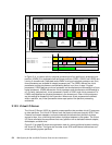
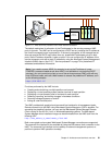
Shared Ethernet adapter
A shared Ethernet adapter (SEA) is a Virtual I/O Server service that acts as a layer 2 network
bridge between a physical Ethernet adapter or aggregation of physical adapters
(EtherChannel) and one or more Virtual Ethernet adapters defined by the Hypervisor on the
Virtual I/O Server. A SEA enables LPARs on the virtual Ethernet to share access to the
physical Ethernet and communicate with stand-alone servers and LPARs on other systems.
The shared Ethernet network provides this access by connecting the internal Hypervisor
VLANs with the VLANs on the external switches. Because the shared Ethernet network
processes packets at layer 2, the original MAC address and VLAN tags of the packet are
visible to other systems on the physical network. IEEE 802.1 VLAN tagging is supported.
The virtual Ethernet adapters that are used to configure a shared Ethernet adapter are
required to have the trunk setting enabled. The trunk setting causes these virtual Ethernet
adapters to operate in a special mode, so that they can deliver and accept external packets
from the POWER5+ internal switch to the external physical switches. The trunk setting should
only be used for the virtual Ethernet adapters that are part of a shared Ethernet network setup
in the Virtual I/O server.
A single SEA setup can have up to 16 virtual Ethernet trunk adapters and each virtual
Ethernet trunk adapter can support up to 20 VLAN networks. Therefore, it is possible for a
single physical Ethernet to be shared between 320 internal VLANs. The number of shared
Ethernet adapters that can be set up in a Virtual I/O Server partition is limited only by the
resource availability because there are no configuration limits.
For a more detailed discussion about virtual networking, see:
http://www.ibm.com/servers/aix/whitepapers/aix_vn.pdf
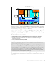
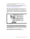
Virtual SCSI
Access to real storage devices is implemented through the virtual SCSI services, a part of the
Virtual I/O Server partition. You accomplish this by using a pair of virtual adapters: a virtual
SCSI server adapter and a virtual SCSI client adapter. The virtual SCSI server and client
adapters are configured using an HMC or through Integrated Virtualization Manager on
smaller systems. The virtual SCSI server (target) adapter is responsible for executing any
SCSI commands it receives. It is owned by the Virtual I/O Server partition. The virtual SCSI
client adapter allows a client partition to access physical SCSI and SAN-attached devices and
LUNs that are assigned to the client partition.
Physical disks owned by the Virtual I/O Server partition can either be exported and assigned
to a client partition as a whole device, or they can be configured into a volume group and
partitioned into several logical volumes. These logical volumes can then be assigned to
individual partitions. From the client partition point of view, these two options are equivalent.
The Virtual I/O Server provides mapping between
backing devices (physical devices or logical
volumes assigned to client partitions in VIOS nomenclature) and client partitions by a
command line interface. The appropriate command is the mkvdev command. For syntax and
semantics, see Virtual I/O Server documentation.
All current storage device types, such as SAN, SCSI, and RAID are supported. SSA and
iSCSI are not supported at the time of writing.
For more information about the specific storage devices supported, see:
http://techsupport.services.ibm.com/server/vios/home.html