


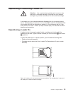
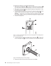
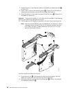

7. Position the tape in the alignment groove of the leader pin attach tool (see 1
in Figure 23).
8. Place a new C-clip into the retention groove 2 (Figure 23) on the leader pin
attachment tool and make sure that the clip’s open side faces up.
9. Place the leader pin (from step 6 on page 59) into the cavity 3 (Figure 23) of
the leader pin attach tool.
Attention: To prevent the leader pin from rolling into the cartridge, in the following
step use care when folding the tape over the pin.
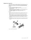
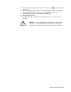
10. Fold the tape over the leader pin and hold it with your fingers (see Figure 23).
Note: Use care to ensure that the tape is centered over the leader pin. Failure
to properly center the tape on the pin will cause the repaired cartridge
to fail. When the tape is properly centered, a 0.25-mm (0.01-in.) gap
exists on both sides of the pin.
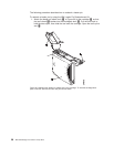
11. Close the pivot arm 4 of the leader pin attach tool by swinging it over the
leader pin so that the C-clip snaps onto the pin and the tape.
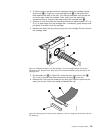
12. Swing the pivot arm open and trim the excess tape 5 so that it is flush with
the reattached leader pin 6.
A67E0037
1
6
2
3
4
5
Figure 23. Attaching the leader pin to the tape
60 IBM TotalStorage LTO Ultrium 2 Tape Drive