


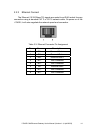

2.4.2 CAN bus indicator LED
The i-7540D includes three single-color LED displays to indicate the status of
module, network and I/O device. They are ER LED (it is red), TX LED (it is green),
and RX LED (it is red). The Indicators assist maintenance personnel in quickly
identifying a problem unit. The LED test is to be performed at power–up. When
the CAN communication events occur, these indicators will be triggered to glitter
with different conditions.
z ER LED
This LED provides device status and indicates whether or not the device is
operating properly. Table 2-6 shows the conditions of ER status. Therefore, when
the device is operated normally, the ER-LED must be turned off. If this led flashing
red, users can use the “99S” command, in section 4.5, to read the status of the
i-7540D.
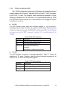
Table 2-6 ER-LED conditions
Condition Description
Off Device is normal; no error occurs
Red Device has unrecoverable fault
Flashing red Device has recoverable fault.
To recover:
Reset device or perform error recovery
z TX LED
This LED indicates the status of message transmitted. Table 2-7 shows the
conditions of TX status. Therefore, when the device transmits messages to the
CAN bus, the TX-LED is normally flashing green.
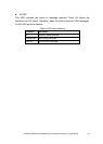
Table 2-7 TX led conditions
Condition Description
Off No data is being transmitted to the CAN side
Flashing green Data are transmitting to the CAN side
Solid green Transmit data error
i-7540D CAN-Ethernet Gateway User’s Manual (Version 1.4, April/2008)
18