


R
4 Intel
®
955X Express Chipset Thermal/Mechanical Design Guide
Figures
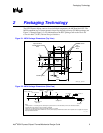
Figure 2-1. MCH Package Dimensions (Top View)............................................................9
Figure 2-2. MCH Package Dimensions (Side View)...........................................................9
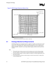
Figure 2-3. MCH Package Dimensions (Bottom View).....................................................10
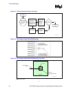
Figure 5-1. Thermal Solution Decision Flowchart.............................................................16
Figure 5-2. Zero Degree Angle Attach Methodology........................................................16
Figure 5-3. Zero Degree Angle Attach Methodology (Top View)......................................16
Figure 6-1. Reference Heatsink Measured Thermal Performance versus Approach
Velocity ......................................................................................................................18
Figure 6-2. Heatsink Volumetric Envelope for the MCH...................................................19
Figure 6-3. MCH Heatsink Board Component Keep-out ..................................................20
Figure 6-4. Retention Mechanism Component Keep-out Zones ......................................21
Figure 6-5. Plastic Wave Soldering Heatsink Assembly...................................................22
Figure 6-6. Plastic Wave Soldering Heatsink Extrusion Profile........................................23
Figure 8-1. Plastic Wave Soldering Heatsink Assembly Drawing ....................................30
Figure 8-2. Plastic Wave Soldering Heatsink Drawing (1 of 2)........................................31
Figure 8-3. Plastic Wave Soldering Heatsink Drawing (2 of 2)........................................32
Figure 8-4. Plastic Wave Soldering Heatsink Ramp Clip Drawing (1 of 2).......................33
Figure 8-5. Plastic Wave Soldering Heatsink Ramp Clip Drawing (2 of 2).......................34
Figure 8-6. Plastic Wave Soldering Heatsink Wire Clip Drawing .....................................35
Figure 8-7. Plastic Wave Soldering Heatsink Solder-Down Anchor Drawing ..................36
Tables
Table 3-1. MCH Thermal Specifications...........................................................................11
Table 6-1 Honeywell PCM 45F TIM Performance as a Function of Attach Pressure ......24
Table 6-2. Reliability Guidelines .......................................................................................25
Table 7-1. MCH Heatsink Thermal Solution .....................................................................27
Table 8-1. Mechanical Drawing List..................................................................................29