


Packaging Technology
R
Intel
®
955X Express Chipset Thermal/Mechanical Design Guide 9
2 Packaging Technology
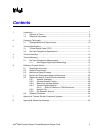
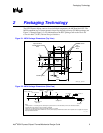
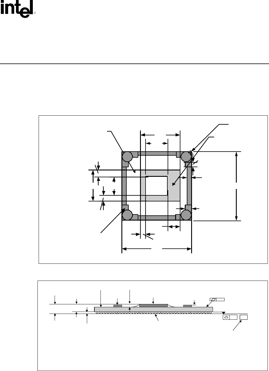
The 955X Express chipset consists of two individual components: the MCH and the ICH7. The
MCH component uses a 34 mm squared, 6-layer flip chip ball grid array (FC-BGA) package (see
Figure 2-1 through Figure 2-3). For information on the ICH7 package, refer to the Intel
®
I/O
Controller Hub 7 (ICH7) Thermal Design Guidelines.
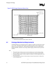
Figure 2-1. MCH Package Dimensions (Top View)
34.00
34.00
Die
Keepout
Area
19.38
Capacitor Area,
Handling Exclusion
Zone
MCH
Die
15.34 9.14
10.67
3.1
3.1
6.17
2.54
Ø5.20mm
2.30
3.0
2.0
Handling Area
955X_Pkg_TopView
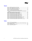
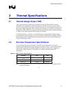
Figure 2-2. MCH Package Dimensions (Side View)
Notes:
1. Primary datum -C- and seating plan are defined by the spherical crowns of the solder balls (show n before motherboard attach)
2. All dimensions and tolerances conform to ANSI Y14.5M-1994
3. BGA has a pre-SMT height of 0.5mm and post-SMT height of 0.41-0.46mm
4. Shown before motherboard attach; FCBGA has a convex (dome shaped) orientation before reflow and is expected to have a slightly concave (bow l
s haped) orientation af ter ref low
0.20 –C–
Die
Substrate
0.435 ± 0.025 mm
See note 3
Seating Plane
1.92 ± 0.078 mm
See note 1.
Decoup
Cap
0.7 mm Max
2.355 ± 0.082 mm
0.84 ± 0.05 mm
0.20 See note 4.
955X_Pkg_SideView