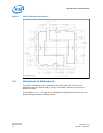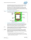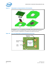
• Desktop ILM back plate using marking “115XDBP” versus server ILM back plate
using marking “115XSBP”.
Note: When reworking a BGA component or the socket that the heatsink, battery, ILM and
ILM back plate are removed prior to rework. The ILM back plate should also be
removed when reworking through hole mounted components in a mini-wave or solder
pot). The maximum temperature for the pre-applied insulator on the ILM is
approximately 106 °C.
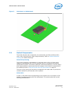
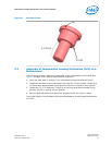
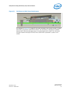
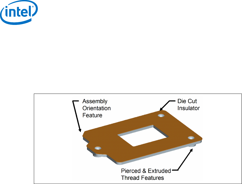
Figure 7. Back Plate
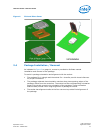
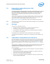
Shoulder Screw and Fasteners Design Overview
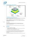
The shoulder screw is fabricated from carbonized steel rod. The shoulder height and
diameter are integral to the mechanical performance of the ILM. The diameter
provides alignment of the load plate. The height of the shoulder ensures the proper
loading of the IHS to seat the processor on the socket contacts. The design assumes
the shoulder screw has a minimum yield strength of 235 MPa.
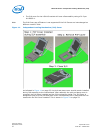
The screws for Server ILM are different from Desktop design. The length of Server ILM
screws are shorter than the Desktop screw length to satisfy Server secondary-side
clearance limitation. Server ILM back plate to use black nickel plated screws, whereas
desktop ILM back plate to use clear plated screws. Unique part numbers, please refer
to Table 7 on page 28.
Note: The reference design incorporates a T-20 Torx* head fastener. The Torx* head
fastener was chosen to ensure end users do not inadvertently remove the ILM
assembly and for consistency with the LGA1366 socket ILM.
LGA1150 Socket—Independent Loading Mechanism (ILM)
LGA1150 Socket
Application Guide September 2013
18 Order No.: 328999-002


