


Intel Desktop Board D925XCV/D925XBC Technical Product Specification
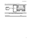
1.7.3 Real-Time Clock, CMOS SRAM, and Battery
A coin-cell battery (CR2032) powers the real-time clock and CMOS memory. When the computer
is not plugged into a wall socket, the battery has an estimated life of three years. When the
computer is plugged in, the standby current from the power supply extends the life of the battery.
The clock is accurate to ± 13 minutes/year at 25 ºC with 3.3 VSB applied.
✏ NOTE
If the battery and AC power fail, custom defaults, if previously saved, will be loaded into CMOS
RAM at power-on.
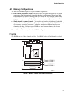
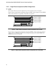
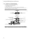
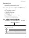
1.8 PCI Express Connectors
The boards provide the following PCI Express connectors:
• One PCI Express x16 connector. The x16 interface supports simultaneous (full duplex) transfer
speeds up to 8 GBytes/sec. Single-ended (half duplex) transfers are supported at up to
4 Gbytes/sec.
• Four PCI Express x1 connectors on the D925XCV board; two PCI Express x1 connectors on
the D925XBC board. The x1 interfaces support simultaneous transfer speeds up to
500 MBytes/sec
The PCI Express interface supports the PCI Conventional bus configuration mechanism so that the
underlying PCI Express architecture is compatible with PCI Conventional compliant operating
systems. Additional features of the PCI Express interface includes the following:
• Support for the PCI Express enhanced configuration mechanism
• Automatic discovery, link training, and initialization
• Support for Active State Power Management (ASPM)
• SMBus 2.0 support
• Wake# signal supporting wake events from ACPI S1, S3, S4, or S5
• Software compatible with the PCI Power Management Event (PME) mechanism defined in the
PCI Power Management Specification Rev. 1.1
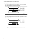
1.9 Auxiliary Power (AUX PWR) Output Connector
The D925XCV board includes a 1x4 power connector that can be used to provide power for
internal chassis lighting or additional fans. The use of this connector requires an ATX12V power
supply with a 24-pin (2x12) main power cable. If a power supply with a 20-pin (2x10) main power
cable is used, the auxiliary power output connector may not function.
The on/off function of this connector is controlled from within the BIOS Setup Program. The
default setting in the BIOS is for this connector to be off.
28