


Technical Reference
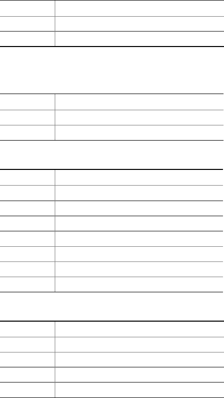
Table 25. Chassis Intrusion Connector
Pin Signal Name
1 Intruder
2 Ground
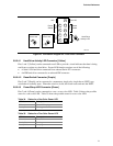
Table 26. SCSI Hard Drive Activity LED
Connector (Optional)
Pin Signal Name
1 SCSI_ACT#
2 No connect
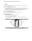
Table 27. Serial ATA Connectors
Pin Signal Name
1 Ground
2 TXP
3 TXN
4 Ground
5 RXN
6 RXP
7 Ground
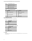
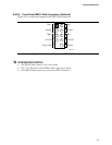
Table 28. Auxiliary Power Output Connector
Pin Signal Name
1 +12 V
2 Ground
3 Ground
4 +5 V
✏
NOTE
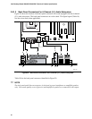
The auxiliary power output connector is present only on the D925XCV board. It is not present on
the D925XBC board.
73