


Technical Reference
Purple
OM17000
Hard Drive
Activity LED
Reset
Switch
+5 V DCN/C
Power
Switch
8
6
4
2
9
7
5
3
1
−
+
Single-colored
Power LED
−
+
Dual-colored
Power LED
+
−
Yellow
Green Red
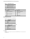
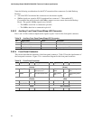
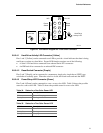
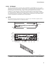
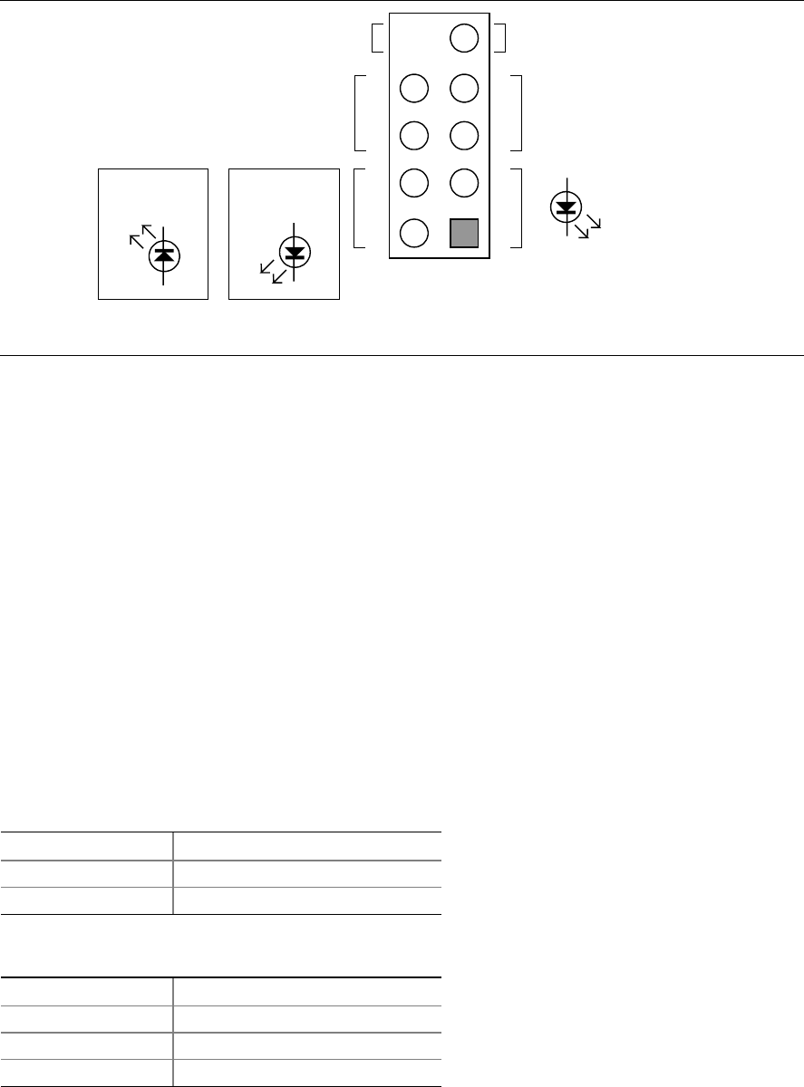
Figure 23. Connection Diagram for Front Panel Connector
2.8.2.4.1 Hard Drive Activity LED Connector [Yellow]
Pins 1 and 3 [Yellow] can be connected to an LED to provide a visual indicator that data is being
read from or written to a hard drive. Proper LED function requires one of the following:
• A Serial ATA hard drive connected to an onboard Serial ATA connector
• An IDE hard drive connected to an onboard IDE connector
2.8.2.4.2 Reset Switch Connector [Purple]
Pins 5 and 7 [Purple] can be connected to a momentary single pole, single throw (SPST) type
switch that is normally open. When the switch is closed, the board resets and runs the POST.
2.8.2.4.3 Power/Sleep LED Connector [Green]
Pins 2 and 4 [Green] can be connected to a one- or two-color LED. Table 34 shows the possible
states for a one-color LED. Table 35 shows the possible states for a two-color LED.
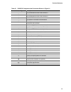
Table 34. States for a One-Color Power LED
LED State Description
Off Power off/sleeping
Steady Green Running
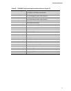
Table 35. States for a Two-Color Power LED
LED State Description
Off Power off
Steady Green Running
Steady Yellow Sleeping
77