


Technical Reference
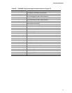
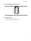
Table 29. Main Power Connector
Pin Signal Name Pin Signal Name
1 +3.3 V 13 +3.3 V
2 +3.3 V 14 -12 V
3 Ground 15 Ground
4 +5 V 16 PS-ON# (power supply remote on/off)
5 Ground 17 Ground
6 +5 V 18 Ground
7 Ground 19 Ground
8 PWRGD (Power Good) 20 No connect
9 +5 V (Standby) 21 +5 V
10 +12 V 22 +5 V
11 +12 V 23 +5 V
12 2x12 connector detect 24 Ground
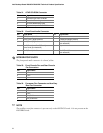
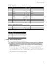
Table 30. ATX12V Power Connector
Pin Signal Name Pin Signal Name
1 Ground 2 Ground
3 +12 V 4 +12 V
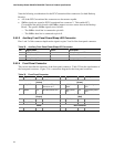
Table 31. Alternate Power Connector
Pin Signal Name
1 +12 V
2 Ground
3 Ground
4 +5 V
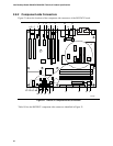
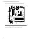
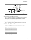
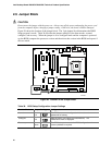
2.8.2.2 Add-in Card Connectors
The board has the following add-in card connectors:
• PCI Express x16: one connector supporting simultaneous transfer speeds up to 8 GBytes/sec
• PCI Express x1: the D925XCV board has two PCI Express x1 connectors; the D925XBC
board has one PCI Express x1 connector. The x1 interfaces support simultaneous transfer
speeds up to 500 MBytes/sec.
• PCI Conventional (rev 2.2 compliant) bus: the D925XCV board has four PCI Conventional
bus add-in card connectors; the D925XBC board has two PCI Conventional add-in card
connectors. The SMBus is routed to PCI Conventional bus connector 2 only (ATX expansion
slot 6). PCI Conventional bus add-in cards with SMBus support can access sensor data and
other information residing on the Desktop Board.
75