


Contents
14. PCI Configuration Space Map......................................................................................59
15. Interrupts......................................................................................................................60
16. PCI Interrupt Routing Map ...........................................................................................62
17. Back Panel Connectors Shown in Figure 19................................................................65
18. Back Panel Connectors Shown in Figure 20................................................................67
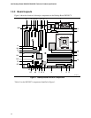
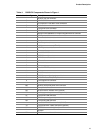
19. D925XCV Component-side Connectors Shown in Figure 21. .....................................69
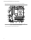
20. D925XBC Component-side Connectors Shown in Figure 22. .....................................71
21. ATAPI CD-ROM Connector .........................................................................................72
22. Front Panel Audio Connector.......................................................................................72
23. Front Chassis Fan and Rear Chassis Fan Connectors...............................................72
24. Processor Fan Connector and Auxiliary Rear Fan Connector....................................72
25. Chassis Intrusion Connector........................................................................................73
26. SCSI Hard Drive Activity LED Connector (Optional)....................................................73
27. Serial ATA Connectors.................................................................................................73
28. Auxiliary Power Output Connector...............................................................................73
29. Main Power Connector.................................................................................................75
30. ATX12V Power Connector...........................................................................................75
31. Alternate Power Connector..........................................................................................75
32. Auxiliary Front Panel Power/Sleep LED Connector.....................................................76
33. Front Panel Connector.................................................................................................76
34. States for a One-Color Power LED..............................................................................77
35. States for a Two-Color Power LED..............................................................................77
36. BIOS Setup Configuration Jumper Settings.................................................................80
37. DC Loading Characteristics .........................................................................................85
38. Fan Connector Current Capability................................................................................86
39. Thermal Considerations for Components ....................................................................89
40. Desktop Board D925XCV/D925XBC Environmental Specifications ............................90
41. Safety Regulations.......................................................................................................91
42. EMC Regulations .........................................................................................................91
43. Product Certification Markings .....................................................................................94
44. BIOS Setup Program Menu Bar...................................................................................96
45. BIOS Setup Program Function Keys............................................................................96
46. Boot Device Menu Options ..........................................................................................99
47. Supervisor and User Password Functions.................................................................101
48. BIOS Error Messages ................................................................................................103
49. Uncompressed INIT Code Checkpoints.....................................................................105
50. Boot Block Recovery Code Checkpoints ...................................................................105
51. Runtime Code Uncompressed in F000 Shadow RAM...............................................106
52. Bus Initialization Checkpoints ....................................................................................109
53. Upper Nibble High Byte Functions.............................................................................109
54. Lower Nibble High Byte Functions.............................................................................110
55. Beep Codes ...............................................................................................................111
ix