


Intel Desktop Board D925XCV/D925XBC Technical Product Specification
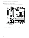
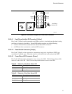
Note the following considerations for the PCI Conventional bus connectors (for both Desktop
Boards):
• All of the PCI Conventional bus connectors are bus master capable.
• SMBus signals are routed to PCI Conventional bus connector 2. This enables PCI
Conventional bus add-in boards with SMBus support to access sensor data on the Desktop
Board. The specific SMBus signals are as follows:
The SMBus clock line is connected to pin A40.
The SMBus data line is connected to pin A41.
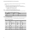
2.8.2.3 Auxiliary Front Panel Power/Sleep LED Connector
Pins 1 and 3 of this connector duplicate the signals on pins 2 and 4 of the front panel connector.
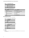
Table 32. Auxiliary Front Panel Power/Sleep LED Connector
Pin Signal Name In/Out Description
1 HDR_BLNK_GRN Out Front panel green LED
2 Not connected
3 HDR_BLNK_YEL Out Front panel yellow LED
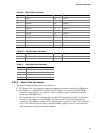
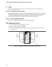
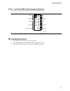
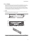
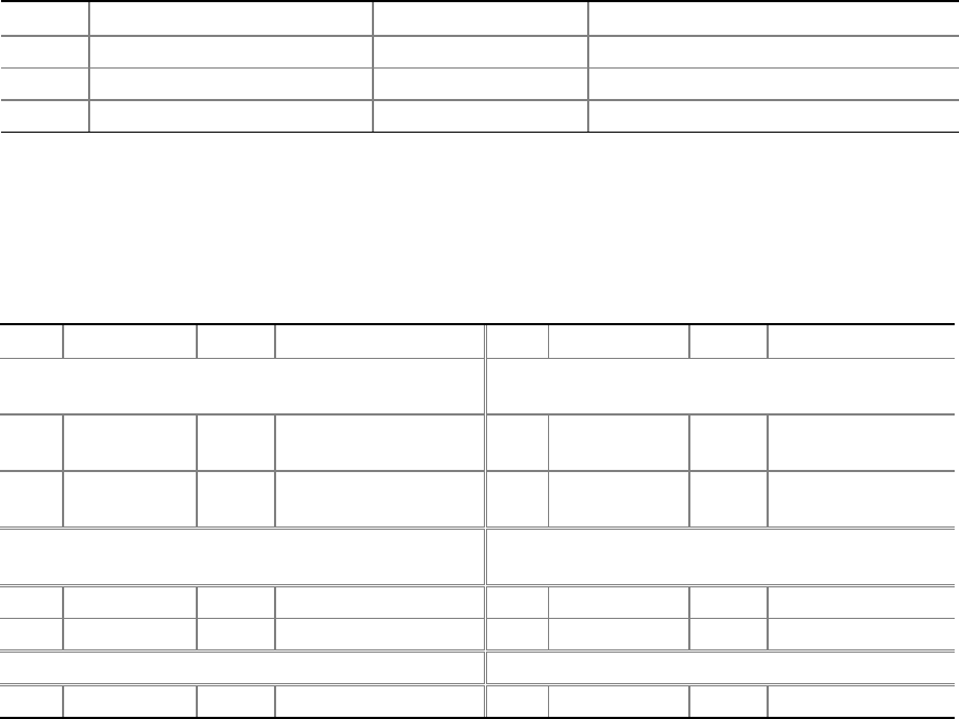
2.8.2.4 Front Panel Connector
This section describes the functions of the front panel connector. Table 33 lists the signal names of
the front panel connector. Figure 23 is a connection diagram for the front panel connector.
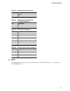
Table 33. Front Panel Connector
Pin Signal In/Out Description Pin Signal In/Out Description
Hard Drive Activity LED
[Yellow]
Power LED
[Green]
1 HD_PWR Out Hard disk LED pull-up
(750 Ω) to +5 V
2 HDR_BLNK_
GRN
Out Front panel green
LED
3 HAD# Out Hard disk active LED 4 HDR_BLNK_
YEL
Out Front panel yellow
LED
Reset Switch
[Purple]
On/Off Switch
[Red]
5 Ground Ground 6 FPBUT_IN In Power switch
7 FP_RESET# In Reset switch 8 Ground Ground
Power Not Connected
9 +5 V Power 10 N/C Not connected
76