


Intel Desktop Board D925XCV/D925XBC Technical Product Specification
✏ NOTE
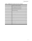
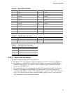
The colors listed in Table 34 and Table 35 are suggested colors only. Actual LED colors are
product- or customer-specific.
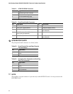
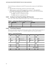
2.8.2.4.4 Power Switch Connector [Red]
Pins 6 and 8 [Red] can be connected to a front panel momentary-contact power switch. The switch
must pull the SW_ON# pin to ground for at least 50 ms to signal the power supply to switch on or
off. (The time requirement is due to internal debounce circuitry on the board.) At least two
seconds must pass before the power supply will recognize another on/off signal.
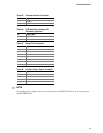
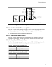
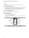
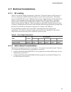
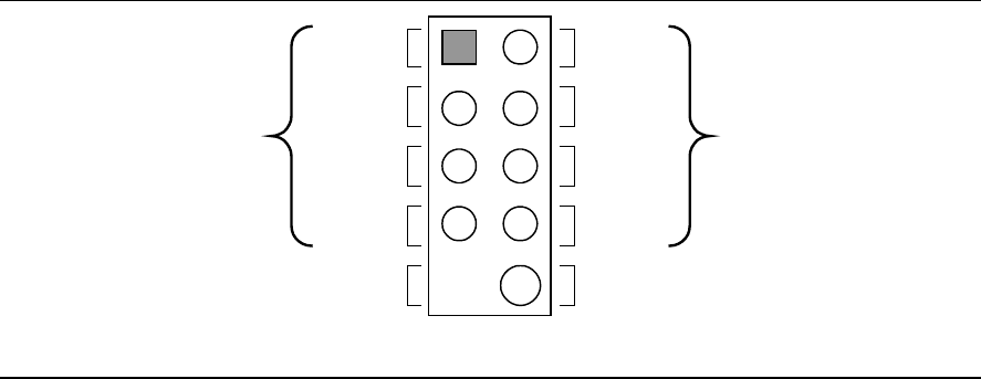
2.8.2.5 Front Panel USB Connectors
Figure 24 is a connection diagram for the front panel USB connectors.
#
INTEGRATOR’S NOTES
• The +5 V DC power on the USB connector is fused.
• Pins 1, 3, 5, and 7 comprise one USB port.
• Pins 2, 4, 6, and 8 comprise one USB port.
• Use only a front panel USB connector that conforms to the USB 2.0 specification for high-
speed USB devices.
OM15963
8
6
4
2
7
5
3
1
Key (no pin)
No Connect
10
Power
(+5 V DC)
D−
D+
Ground
D+
Ground
D−
Power
(+5 V DC)
One
USB
Port
One
USB
Port
Figure 24. Connection Diagram for Front Panel USB Connectors
78