


Technical Reference
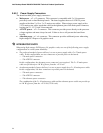
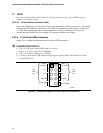
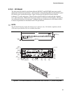
2.8.2.6 Front Panel IEEE 1394a Connectors (Optional)
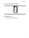
Figure 25 is a connection diagram for the IEEE 1394a connectors.
OM16107
8
6
4
2
7
5
3
1
Key (no pin)
10
TPA+
+12 V DC
TPA−
Ground
TPB+ TPB−
Ground
Ground
+12 V DC
Figure 25. Connection Diagram for IEEE 1394a Connectors
#
INTEGRATOR’S NOTES
• The IEEE 1394a connectors are colored blue.
• The +12 V DC power on the IEEE 1394a connectors is fused.
• Each IEEE 1394a connector provides one IEEE 1394a port.
79